● Zone 1 reach settings for phase-faults and earth-faults
● Zone 2 reach settings for phase-faults and earth-faults
● Zone 3 reach settings for phase-faults and earth-faults
● Zone 3 reverse reach settings
● Zone 4 reach settings (for use with Permissive Overreach or Blocking schemes if needed)
● Load avoidance
The settings are applicable whether the Distance protection characteristics are set to Mho, or Quadrilateral. If you
choose Quadrilateral however, you will need to consider the Resistive reaches of Quadrilaterals.
For this study, we wish to protect one line of a double 230kV, 100km line between a substation at Green Valley and
a substation at Blue river. There are generating sources at Tiger Bay, 80 km from Green Valley and at Rocky Bay, 60
km from Blue River.
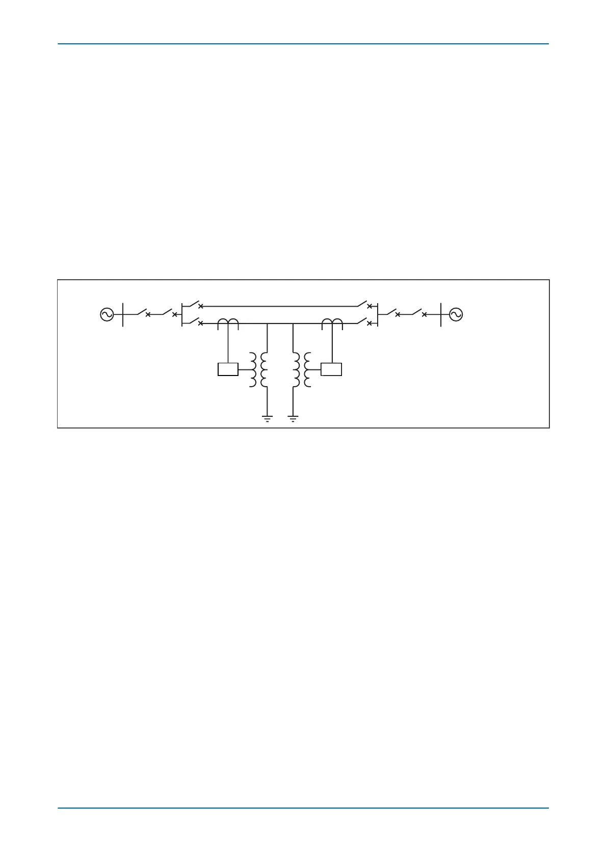
The single-line diagram for the system is shown in the following figure:
Tiger Bay
Green Valley Blue River
Rocky Bay
80 km
100 km
60 km
IED IED
E02705
Figure 68: Example power system
The system data is as follows:
● System Voltage: 230kV
● System earthing: Solid
● CT ratio: 1200 : 5
● VT ratio: 230 000 : 115
● Line length: 100km
●
Positive sequence line impedance (Z1): 0.089 + j0.476 ohms/km = 0.484Ð79.4°
●
Zero sequence line impedance (Z0): 0.426 + j1.576 ohms/km = 1.632Ð74.8°
●
Z0/Z1: 3.372Ð4.6°
● Green Valley substation fault level: 2000 MVA to 5000 MVA
● Blue river substation fault level: 1000 MVA to 3000 MVA
● Circuit continuous rating: 400 MVA
● Worst case power factor of load: 0.85
6.11.1
LINE IMPEDANCE CALCULATION
Ratio of secondary to primary impedance = (1200/5)/(230000/115) = 0.12
Total primary line impedance (for 100 km length) = 100 x 0.484
Ð
79.4°
W
Total secondary impedance = (0.12 x 100 x 0.484)
Ð
79.4° = 5.81
Ð
79.4°
W
Therefore set secondary values as follows:
Line Angle = 80°
Chapter 7 - Distance Protection P446SV
158 P446SV-TM-EN-1