7-48 PQM Power Quality Meter GE Power Management
7.3 MODBUS MEMORY MAP 7 MODBUS COMMUNICATIONS
7
THD
ALARMS
continued
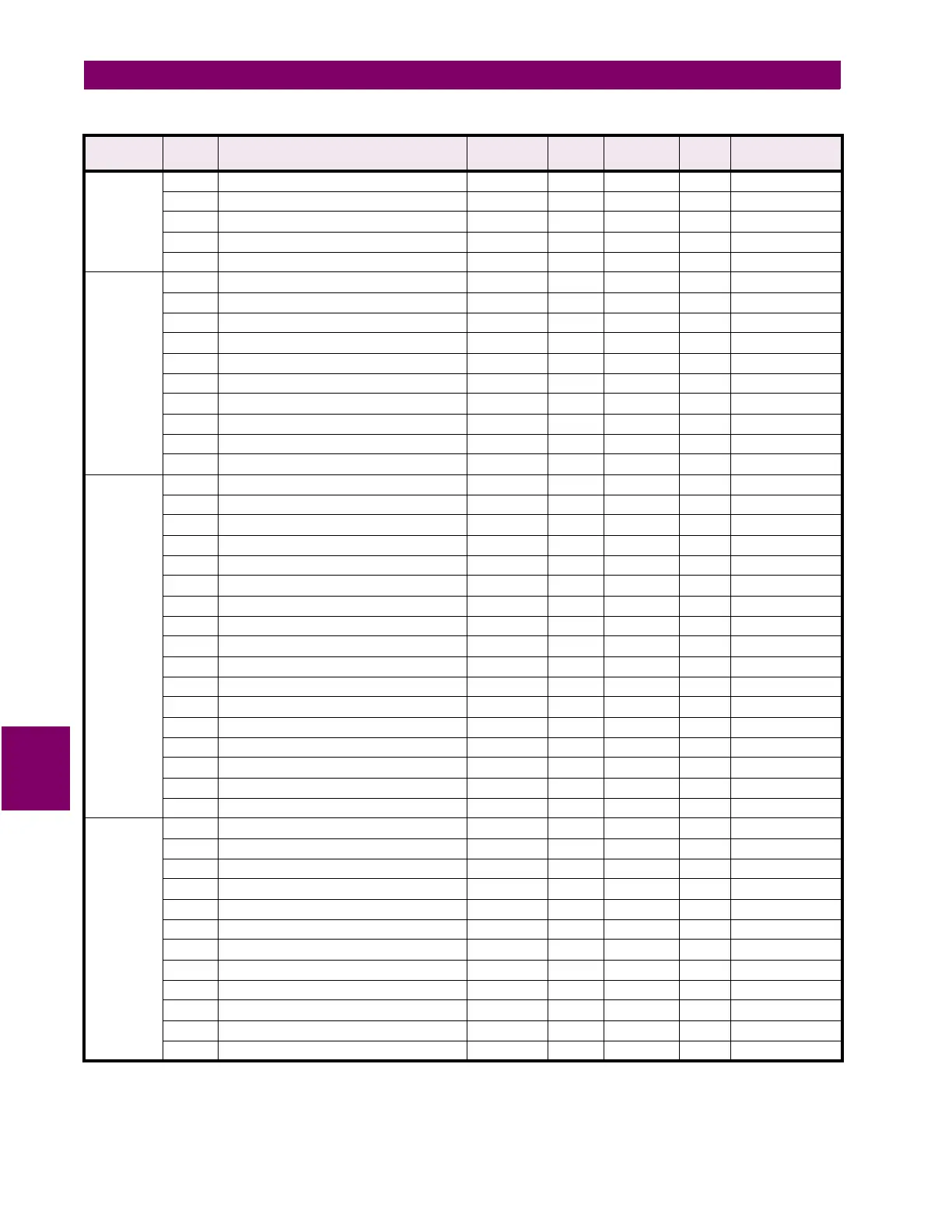
114C Average Voltage THD Level 5 to 1000 5 0.1 x % F1 100=10.0%
114D Average Voltage THD Delay 5 to 6000 5 0.1 x s F1 100=10.0 s
114E Reserved
to
↓
↓
↓
↓
↓
↓
1157 Reserved
FREQUENCY
ALARMS
1158 Underfrequency Relay 0 to 4 1 --- F29 0=OFF
1059 Underfrequency Level 2000 to 7000 1 0.01 x Hz F1 40.00 Hz
115A Underfrequency Delay 1 to 100 1 0.1 x s F1 100=10.0 s
115B Zero Frequency Detect 0 to 1 1 --- F11 0=DISABLE
115C Overfrequency Relay 0 to 4 1 --- F29 0=OFF
115D Overfrequency Level 2000 to 12500 1 0.01 x Hz F1 70.00 Hz
115E Overfrequency Delay 1 to 100 1 0.1 x s F1 100=10.0 s
115F Reserved
to
↓
↓
↓
↓
↓
↓
1166 Reserved
POWER
ALARMS
1167 Power Alarms Level Base Units 0 to 1 1 --- F114 0=kW/kVAR
1168 Positive Real Power Relay 0 to 4 1 --- F29 0=OFF
1169 Positive Real Power Level in kW 1 to 65000 1 kW F1 1000 kW
116A Positive Real Power Delay 5 to 6000 5 0.1 x s F1 100=10.0 s
116B Negative Real Power Relay 0 to 4 1 --- F29 0=OFF
116C Negative Real Power Level in kW 1 to 65000 1 kW F1 1000 kW
116D Negative Real Power Delay 5 to 6000 5 0.1 x s F1 100=10.0 s
116E Positive Reactive Power Relay 0 to 4 1 --- F29 0=OFF
116F Positive Reactive Power Level in kVAR 1 to 65000 1 kVAR F1 1000 kVAR
1170 Positive Reactive Power Delay 5 to 6000 5 0.1 x s F1 100=10.0 s
1171 Negative Reactive Power Relay 0 to 4 1 --- F29 0=OFF
1172 Negative Reactive Power Level in kVAR 1 to 65000 1 kVAR F1 1000 kVAR
1173 Negative Reactive Power Delay 5 to 6000 5 0.1 x s F1 100=10.0 s
1174 Positive Real Power Level in MW 1 to 65000 1 0.01 MW F1 10.00MW
1175 Negative Real Power Level in MW 1 to 65000 1 0.01 MW F1 10.00MW
1176 Positive Reactive Power Level in MVAR 1 to 65000 1 0.01 MVAR F1 10.00MVAR
1177 Negative Reactive Power Level in MVAR 1 to 65000 1 0.01 MVAR F1 10.00MVAR
POWER
FACTOR
ALARMS
1178 Power Factor Lead 1 Relay 0 to 4 1 --- F29 0=OFF
1179 Power Factor Lead 1 Pickup Level 0 to 100 1 0.01 x PF F1 1.00
117A Power Factor Lead 1 Dropout Level 0 to 100 1 0.01 x PF F1 1.00
117B Power Factor Lead 1 Delay 5 to 6000 5 0.1 x s F1 100=10.0 s
117C Power Factor Lag 1 Relay 0 to 4 1 --- F29 0=OFF
117D Power Factor Lag 1 Pickup Level 0 to 100 1 0.01 x PF F1 1.00
117E Power Factor Lag 1 Dropout Level 0 to 100 1 0.01 x PF F1 1.00
117F Power Factor Lag 1 Delay 5 to 6000 5 0.1 x s F1 100=10.0 s
1180 Power Factor Lead 2 Relay 0 to 4 1 --- F29 0=OFF
1181 Power Factor Lead 2 Pickup Level 0 to 100 1 0.01 x PF F1 1.00
1182 Power Factor Lead 2 Dropout Level 0 to 100 1 0.01 x PF F1 1.00
1183 Power Factor Lead 2 Delay 5 to 6000 5 0.1 x s F1 100=10.0 s
Table 7–10: PQM MEMORY MAP (Sheet 34 of 40)
GROUP ADDR
(HEX)
DESCRIPTION RANGE STEP
VALUE
UNITS and
SCALE
FORMAT FACTORY DEFAULT
Notes: * Data type depends on the Command Operation Code. ** Any valid Actual Values or Setpoints address.
*** Maximum Setpoint value represents “OFF”. **** Minimum Setpoint value represents “OFF”.
***** Maximum Setpoint value represents “UNLIMITED”.

 Loading...


