GE Power Management PQM Power Quality Meter 7-49
7 MODBUS COMMUNICATIONS 7.3 MODBUS MEMORY MAP
7
POWER
FACTOR
ALARMS
continued
1184 Power Factor Lag 2 Relay 0 to 4 1 --- F29 0=OFF
1185 Power Factor Lag 2 Pickup Level 0 to 100 1 0.01 x PF F1 1.00
1186 Power Factor Lag 2 Dropout Level 0 to 100 1 0.01 x PF F1 1.00
1187 Power Factor Lag 2 Delay 5 to 6000 5 0.1 x s F1 100=10.0 s
1188 Reserved
to
↓
↓
↓
↓
↓
↓
118F Reserved
DEMAND
ALARMS
1190 Phase A Current Demand Relay 0 to 4 1 --- F29 0=OFF
1191 Phase A Current Demand Level 10 to 7500 1 A F1 100 A
1192 Phase B Current Demand Relay 0 to 4 1 --- F29 0=OFF
1193 Phase B Current Demand Level 10 to 7500 1 A F1 100 A
1194 Phase C Current Demand Relay 0 to 4 1 --- F29 0=OFF
1195 Phase C Current Demand Level 10 to 7500 1 A F1 100 A
1196 Neutral Current Demand Relay 0 to 4 1 --- F29 0=OFF
1197 Neutral Current Demand Level 10 to 7500 1 A F1 100 A
1198 Positive Real Power Demand Relay 0 to 4 1 --- F29 0=OFF
1199 Positive Real Power Demand Level 1 to 65000 1 kW F1 1000 kW
119A Positive Reactive Power Demand Relay 0 to 4 1 --- F29 0=OFF
119B Positive Reactive Power Demand Level 1 to 65000 1 kvar F1 1000 kvar
119C Apparent Power Demand Relay 0 to 4 1 --- F29 0=OFF
119D Apparent Power Demand Level 1 to 65000 1 kVA F1 1000 kVA
119E Negative Real Power Demand Relay 0 to 4 1 --- F29 0=OFF
119F Negative Real Power Demand Level 1 to 65000 1 kW F1 1000 kW
11A0 Negative Reactive Power Demand Relay 0 to 4 1 --- F29 0=OFF
11A1 Negative Reactive Power Demand Level 1 to 65000 1 kvar F1 1000 kvar
11A2 Reserved
to
↓
↓
↓
↓
↓
↓
11A7 Reserved
PULSE
INPUT
ALARMS
11A8 Pulse Input 1 Relay 0 to 4 1 --- F29 0=OFF
11A9 Pulse Input 1 Level 1 to 65000 1 --- F1 100
11AA Pulse Input 1 Delay 5 to 6000 5 0.1 x s F1 100=10.0 s
11AB Reserved
to
↓
↓
↓
↓
↓
↓
11AF Reserved
MISC.
ALARMS
11B0 Serial COM1 Failure Alarm Delay 5 to 61*** 1 s F1 61=OFF
11B1 Serial COM2 Failure Alarm Delay 5 to 61*** 1 s F1 61=OFF
11B2 Clock Not Set Alarm 0 to 1 1 --- F11 1 = ENABLE
11B3 Data Log 1 Percentage Full Alarm Level 50 to 101*** 1 s F1 101=OFF
11B4 Data Log 2 Percentage Full Alarm Level 50 to 101*** 1 s F1 101=OFF
11B5 Reserved
11B6 Reserved
11B7 Reserved
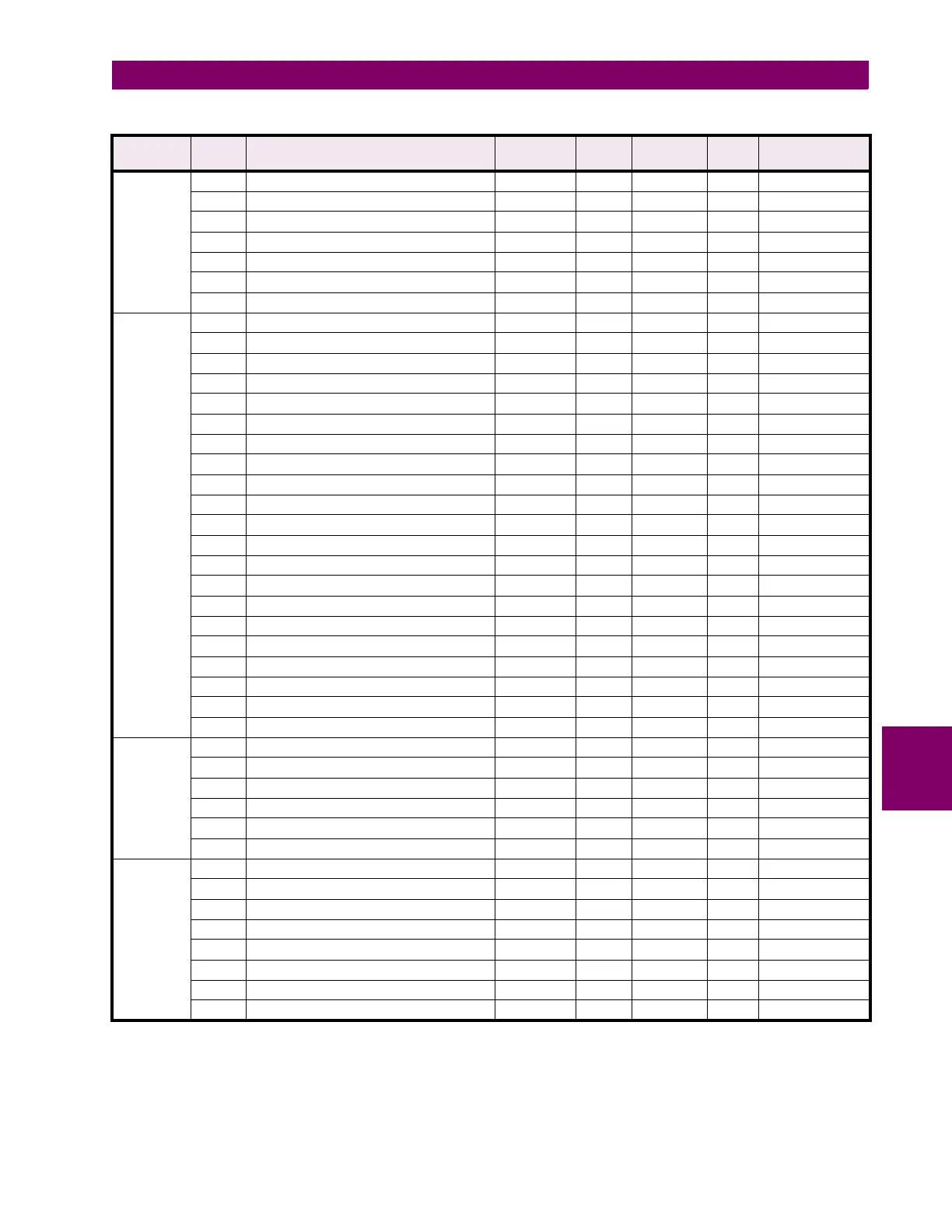
Table 7–10: PQM MEMORY MAP (Sheet 35 of 40)
GROUP ADDR
(HEX)
DESCRIPTION RANGE STEP
VALUE
UNITS and
SCALE
FORMAT FACTORY DEFAULT
Notes: * Data type depends on the Command Operation Code. ** Any valid Actual Values or Setpoints address.
*** Maximum Setpoint value represents “OFF”. **** Minimum Setpoint value represents “OFF”.
***** Maximum Setpoint value represents “UNLIMITED”.

 Loading...


