7-60 PQM Power Quality Meter GE Power Management
7.3 MODBUS MEMORY MAP 7 MODBUS COMMUNICATIONS
7
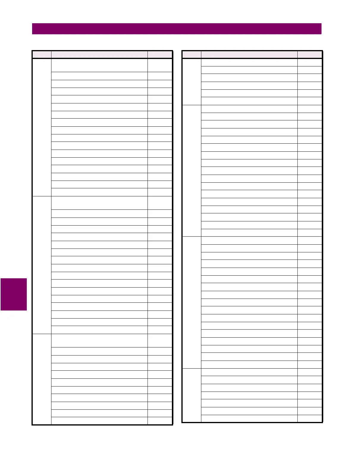
F102 LED STATUS FLAGS:
(0 = INACTIVE, 1 = ACTIVE)
FFFF
AUX 1 Relay 0001
AUX 2 Relay 0002
AUX 3 Relay 0004
ALARM 0008
PROGRAM 0010
SIMULATION 0020
ALARM Relay 0040
SELF TEST 0080
Not Used 0100
Not Used 0200
Not Used 0400
Not Used 0800
Not Used 1000
Not Used 2000
Not Used 4000
Not Used 8000
F103 LED ATTRIBUTE FLAGS
(0 = FLASHING, 1 = SOLID; ACTIVE)
FFFF
AUX 1 Relay 0001
AUX 2 Relay 0002
AUX 3 Relay 0004
ALARM 0008
PROGRAM 0010
SIMULATION 0020
ALARM Relay 0040
SELF TEST 0080
Not Used 0100
Not Used 0200
Not Used 0400
Not Used 0800
Not Used 1000
Not Used 2000
Not Used 4000
Not Used 8000
F104 OUTPUT RELAY FLAG
(0=DE-ENERGIZED,1=ENERGIZED)
FFFF
Alarm Relay 0001
Auxiliary Relay 1 0002
Auxiliary Relay 2 0004
Auxiliary Relay 3 0008
Not Used 0010
Not Used 0020
Not Used 0040
Not Used 0080
Not Used 0100
Not Used 0200
Table 7–11: MEMORY MAP DATA FORMATS (Sheet 11 of 16)
CODE DESCRIPTION BITMASK
F104
con’t
Not Used 0400
Not Used 0800
Not Used 1000
Not Used 2000
Not Used 4000
Not Used 8000
F105 ALARM STATUS FLAGS 1: FFFF
Phase Undercurrent Alarm 0001
Phase Overcurrent Alarm 0002
Neutral Overcurrent Alarm 0004
Undervoltage Alarm 0008
Overvoltage Alarm 0010
Current Unbalance Alarm 0020
Voltage Unbalance Alarm 0040
Voltage Phase Reversal 0080
Power Factor Lead Alarm 1 0100
Power Factor Lead Alarm 2 0200
Power Factor Lag Alarm 1 0400
Power Factor Lag Alarm 2 0800
Positive Real Power Alarm 1000
Negative Real Power Alarm 2000
Positive Reactive Power Alarm 4000
Negative Reactive Power Alarm 8000
F106 ALARM STATUS FLAGS 2: FFFF
Underfrequency Alarm 0001
Overfrequency Alarm 0002
Positive Real Power Demand alarm 0004
Positive Reactive Power Demand Alarm 0008
Apparent Power Demand Alarm 0010
Phase A Current Demand Alarm 0020
Phase B Current Demand Alarm 0040
Phase C Current Demand Alarm 0080
Neutral Current Demand Alarm 0100
Switch A Alarm 0200
Switch B Alarm 0400
Switch C Alarm 0800
Switch D Alarm 1000
Internal Fault Alarm 2000
Serial COM1 Failure Alarm 4000
Serial COM2 Failure Alarm 8000
F107 ALARM STATUS FLAGS 3: FFFF
Clock Not Set Alarm 0001
Parameters Not Set Alarm 0002
Pulse Input 1 Alarm 0004
Current THD Alarm 0008
Voltage THD Alarm 0010
Analog Input Main Alarm 0020
Table 7–11: MEMORY MAP DATA FORMATS (Sheet 12 of 16)
CODE DESCRIPTION BITMASK

 Loading...


