GE Power Management PQM Power Quality Meter 2-11
2 INSTALLATION 2.2 ELECTRICAL
2
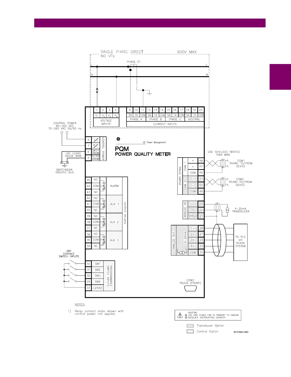
For a single-phase connection, connect current and voltage to the phase A inputs only. All other inputs are
ignored. Select the
S2 SYSTEM SETUP \ CURRENT/VOLTAGE CONFIGURATION \ VT WIRING: SINGLE PHASE
setpoint.
Figure 2–9: SINGLE PHASE CONNECTION

 Loading...


