2-12 PQM Power Quality Meter GE Power Management
2.2 ELECTRICAL 2 INSTALLATION
2
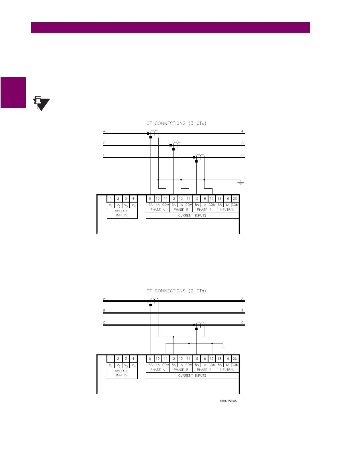
The figure below shows two methods for connecting CTs to the PQM for a 3-wire system. The top drawing
shows the standard wiring configuration using three CTs. An alternate wiring configuration uses only two CTs.
With the two CT method, the third phase is measured by connecting the commons from phase A and C to the
phase B input on the PQM. This causes the phase A and phase C current to flow through the PQM’s phase B
CT in the opposite direction, producing a current equal to the actual phase B current.
I
a
+ I
b
+ I
c
= 0 for a three wire system.
I
b
= – (
I
a
+
I
c
)
For the CT connections above, the
S2 SYSTEM SETUP \ CURRENT/VOLTAGE CONFIGURATION \ PHASE CT
WIRING \ PHASE CT PRIMARY
setpoint must be set to
PHASE A, B, AND C
.
Figure 2–10: ALTERNATE CT CONNECTIONS FOR 3-WIRE SYSTEM
NOTE

 Loading...


