ADV200 • Quick start up guide 85
Step 7 - Speed regulation setting
In this step the basic settings in order to perform a functional test of the drive-
motor system are described. This functional test uses factory settings as far as
the analog and digital commands of the drive are concerned. The regulation
mode is that set in PAR 552 Regulation mode, default is V/f control.
Before starting, check the following setting:
Menu 02 DRIVE INFO, parameter 02.1 Drive series, PAR:480 = Asynchronous.
Menu 04 DRIVE CONFIG, parameter 04.2 Regulation mode, PAR: 552 (default:
0 = V/f control; 1 = Flux vector OL; 2 = Flux vector CL; 3 = Autotune)
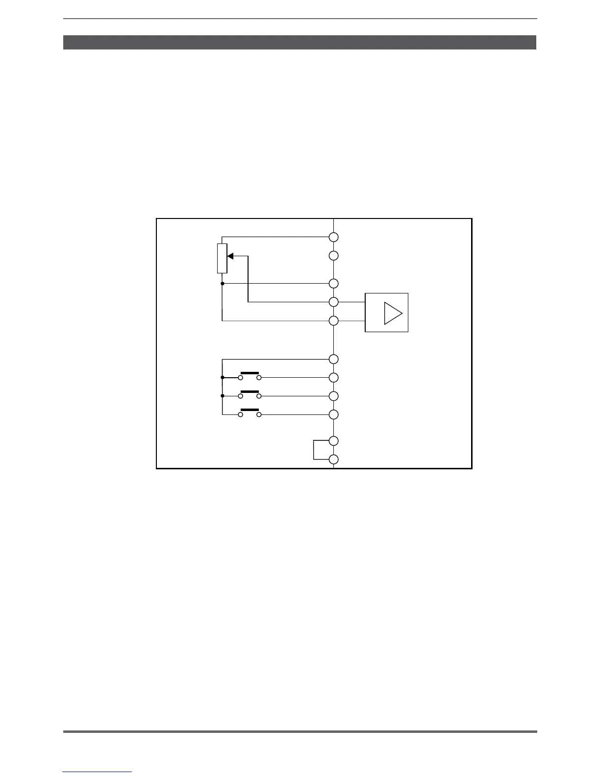
• Basic connections for the speed test
After making the connections described in the previous section, proceed as fol-
lows to start the motor rotating:
1. Make sure the analog signal or potentiometer are set to the minimum value.
2. Close the Enable contact (terminals S3 – 7)
3. Close the FR forward src (PAR 1042) contact, terminals S3 – 8. The drive
starts magnetizing the motor
4. Increase the reference signal gradually using the potentiometer or analog
signal.
5. If the motor rotates anti-clockwise with the FR forward src (PAR 1042) com-
mand and a positive analog reference, stop the drive, disconnect the power
supply and invert two phases between U, V and W.
6. Press the DISP key to check that the voltage, current and output frequency
values are correct in relation to the type of motor and the set speed reference
value.
7. If all the parameters are correct, increase the analog reference to the full scale
value and check that the output voltage is the same as that on the motor data
plate, that the current is approximately equal to the magnetizing current (for
a standard asynchronous motor this is usually between 25% and 40% of the
rated current) and that the output frequency is 50 Hz.

 Loading...


