108 ADL300 • Quick installation guide - Specifications and connection
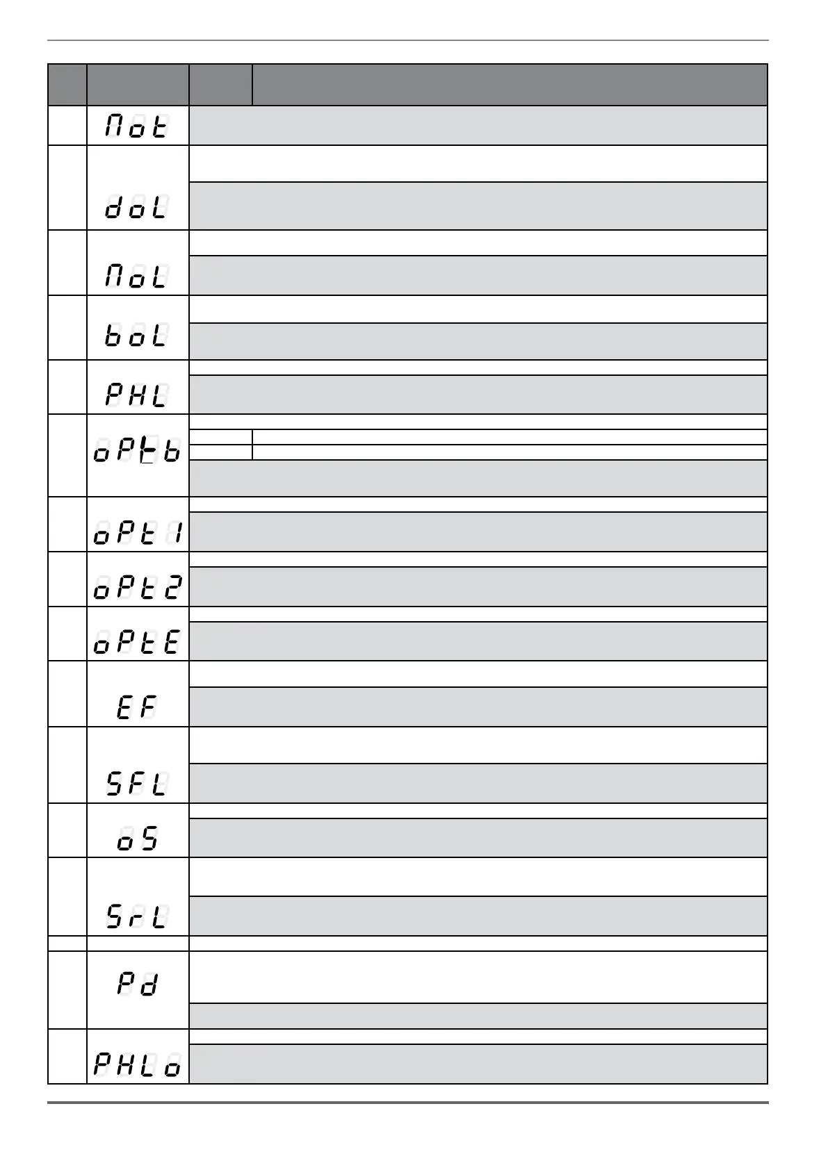
Code Error message shown
on the display [on the
integrated keypad]
Sub-code Description
Solution:
- Change the processing cycle.
- Use a cooling fan to cool the motor.
13 Drive overload [DOL]
Condition: Drive overload alarm.
- The inverter output current has exceeded the allowed overload value.
- The overload cycle has exceeded the allowed values.
Solution:
- Check that the load is not excessive.
- Check that accelerations are not excessive.
- Check that the overload cycle is within allowed limits.
14 Motor overload [MOL]
Condition: Motor overload alarm.
The current absorbed during operation is greater than that specified on the motor data plate.
Solution:
- Reduce the motor load.
- Increase the size of the motor.
15
Bres overload [BOL]
Condition: Braking resistor overload alarm.
The current absorbed by the resistor is greater than the rated current.
Solution:
- Check the size of the braking resistor.
- Check the condition of the braking resistor.
16 Phase loss [PHL] Condition: Power phase loss alarm.
Solution: Check the mains voltage and whether any protections upstream of the drive have been tripped.
17 Opt Bus fault [OPTB] Condition: Error in the configuration stage or communication error.
XXX0H-X If the first digit to the left of “H” in the alarm sub-code is equal to 0, the error relates to a communication problem.
XXXXH-X If the first digit to the left of “H” in the alarm sub-code is other than 0, the error relates to a configuration problem.
Solution: For configuration errors, check the configuration of the Bus communication, Bus type, Baudrate, address. parameter setting
For communication errors verify wiring, resistance of terminations, interference immunity, timeout settings.
For more details reference should be made to the datasheet of the bus being used.
18 Opt 1 IO fault [OPT1] Condition: Error in the communication between Regulation and I/O expansion card in slot 1 (Advanced version only).
Solution: Check that it has been inserted correctly, see Appendix section A.1. (Advanced version only).
19 Opt 2 IO fault Condition: Error in the communication between Regulation and encoder expansion card in slot 2 (Advanced version only).
Solution: Check that it has been inserted correctly, see Appendix section A.1. (Advanced version only).
20 Opt Enc fault [OPTE] Condition: Error in the communication between Regulation and Encoder feedback card (Advanced version only).
Solution: Check that it has been inserted correctly, see Appendix section A.1.
21 External fault [EF]
Condition: External alarm present.
A digital input has been programmed as an external alarm, but the +24V voltage is not available on the terminal.
Solution: Check that the terminal screws are tight
22 Speed fbk loss [SFL]
Condition: Speed feedback loss alarm.
The encoder is not connected, not connected properly or not powered: verify encoder operation by selecting the PAR 260 Motor speed parameter in the
MONITOR menu.
Solution:
See parameter 2172 SpdFbkLoss code for information about the cause of the alarm and chapter 10.2 Speed fbk loss [22] alarm
23 Overspeed [OS] Condition: Motor overspeed alarm. The motor speed exceeds the limits set in the PAR 4540 parameter.
Solution:
- Limit the speed reference.
- Check that the motor is not driven in overspeed during rotation.
24 Speed ref loss [SRL]
Condition: Speed reference loss alarm; occurs if the difference between the speed regulator reference and the actual motor speed is more than
100 rpm. This condition occurs because the drive is in the current limit condition. It is only available in the Flux Vect OL and Flux Vect CL mode (see PAR
4550).
Solution: Check that the load is not excessive.
25 Not Used
26
Power down [PRR]
Condition: The drive was enabled with no supply voltage at the power section.
Solution: Emergency stop alarm. The Stop key on the keypad was pressed with the Stop key mode parameter set to EmgStop&Alarm in case of
Remote->Terminal Strip or Remote->Digital or Local->Terminal Strip mode.
27 Phaseloss out [PHLO] Condition: Output phase loss.
Solution: Check Drive/motor connection.

 Loading...


