36 ADL300 • Quick installation guide - Specifications and connection
Note! The power terminal strip is extractable on sizes 2055 ... 3110. The EM terminal strip is extractable on all mechanical sizes.
Size
ADL300-...-2T,
3ph
Terminals:
on structural work
Cable cross-section
Lock screw diameter
Recommended
terminal
Tightening torque (min)
(mm
2
) AWG (mm) (mm) (Nm)
2055 ... 3110
Same as the maximum cross-section used for the
power terminal strip
M5 Eyelet - Fork 6
4150
16 6 M6 Eyelet - Fork 10
4185
16 6 M6 Eyelet - Fork 10
4220
16 6 M6 Eyelet - Fork 10
5300
50 1/0 M6 Eyelet - Fork 10
5370
50 1/0 M6 Eyelet - Fork 10
Size
ADL300-...-
2M-... , 1ph
Morsetti: L1 - N - BR - C1 - C - D - U - V - W - EM
Maximum cable cross-section
(flexible conductor)
Recommended
stripping
Recommended
terminal
Tightening
torque (min)
(mm
2
) AWG (mm) (mm) (Nm)
1011 4 10 10 None / pin 0.5 ... 0.6
1015 4 10 10 None / pin 0.5 ... 0.6
2022 6 8 10 None / pin 1.2 ... 1.5
2030 6 8 10 None / pin 1.2 ... 1.5
3040 16 6 14 None / pin 1.5 ... 1.7
3055 16 6 14 None / pin 1.5 ... 1.7
Size
ADL300-...-
2M-... , 1ph
Terminals:
on structural work
Cable cross-section
Lock screw diameter
Recommended
terminal
Tightening torque (min)
(mm
2
) AWG (mm) (mm) (Nm)
1011 ... 3055
Same as the maximum cross-section used for the
power terminal strip
M5 Eyelet - Fork 6
Note! The minimum cross-section for both ground connections must comply with EN61800-5-1 prescriptions. Always ground both points on structural steel.
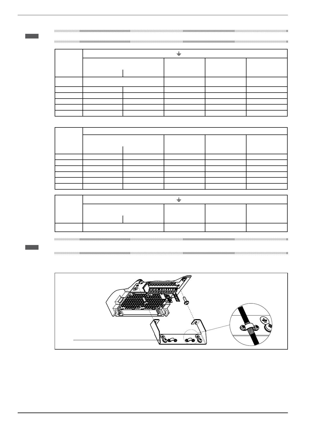
7.1.2 Connection of shielding (recommended)
A
B
C
Optional Power Shield kit:
- Cod. S726101 (sizes 1 and 2)
- Cod. S726501 (size 3)
Loosen the two screws (B), put the metal support (A) (optional, POWER SHIELD KIT) in place and screw down tightly.
Fasten the power cable shield to the omega sections (C) as illustrated in the gure.
• Sizes 4 and 5 : for these sizes the metal support (A) is not provided. Cable shielding must be provided by the installer.

 Loading...


