ADL300 • Quick installation guide - Specifications and connection 55
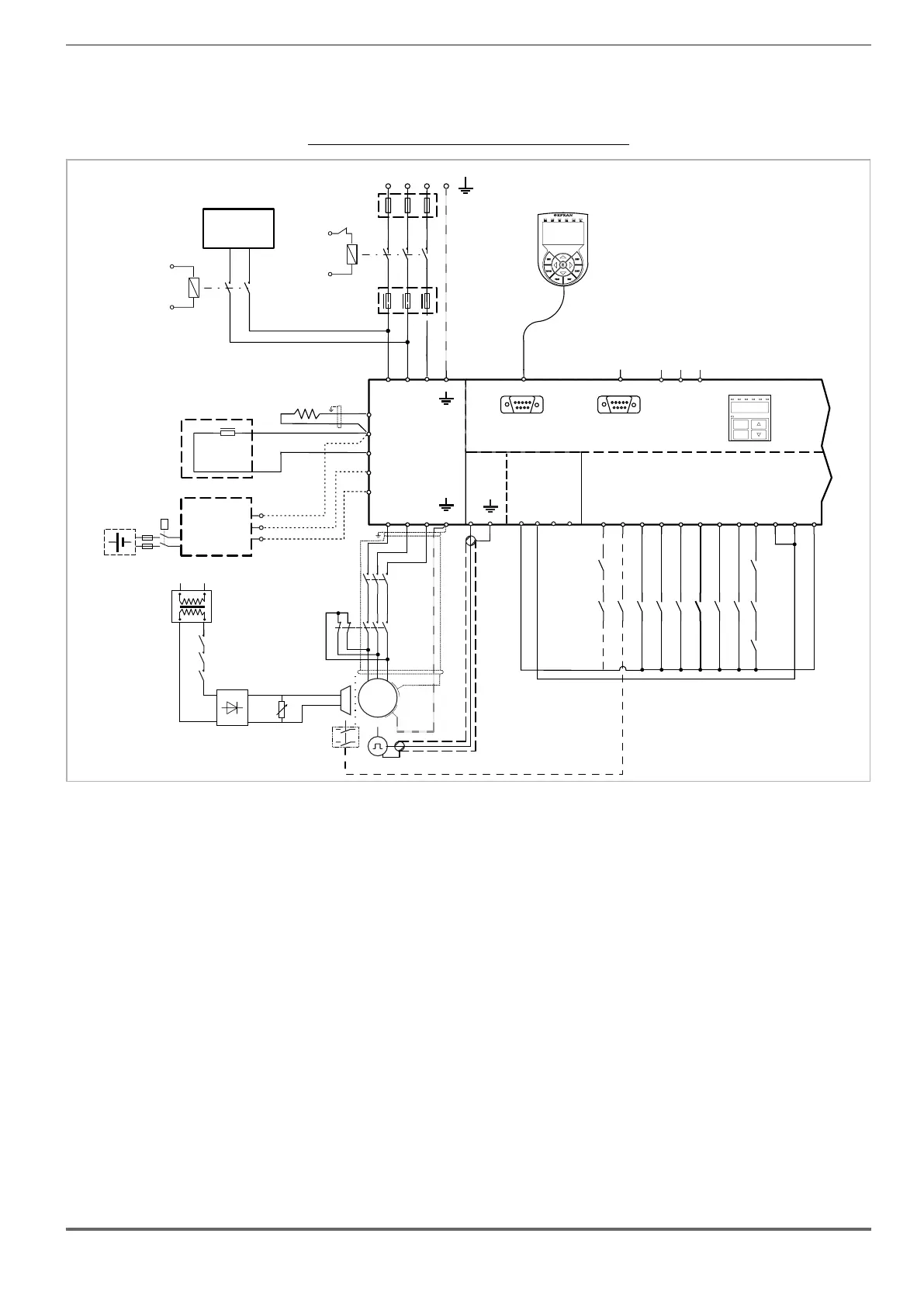
7.3.3 Emergency connection diagram (with UPS or EMS module)
The conguration described in this paragraph can be used to manage the motor in an emergency power failure
condition (with 230 VAC single-phase UPS power supply or EMS module).
Figure 7.3.2.4: Emergency connection diagram (ADL300A-4300 ...4450 sizes)
AC
L1
1
2
S1
3
4
5
6
F1
ADL300A
U1
V1 W1
U2
V2
W2
P-ADL
EXP-IO
R-ADL
RS232
DI8
DI7
DI6
DI5
DI4
DI3
DI2
DI1
ENHW
DICM
0VOUT
24VOUT
L1 L2 L3
KEYPAD / DCP
PC
T1 T2 T3
12345678910 11 12
PE
PE
D
C1
BR
EM
3 PHASE MAINS
BrakeFbk
MltSpd S1
MltSpd S2
Emergency mode
MltSpd S0
StartFwdCmd
StartRevCmd
K2M
K3M
C
S2
US1
S2
US2
UPS
1ph, 230V
50Hz
DC
L1
EMERGENCY
MODE
SUPPLIER
OPTIONAL
BREAKING
RESISTORS
OPTIONAL
C
D
EM
DC CHOKE
Battery Pack
+
_
EMS (*)
KB
M
3
~
5
6
3
4
1
2
K2M
5
6
3
4
1
2
K3M
BRAKE
BR
FBK
-
+
~
~
K3M
K2M
Safety
chain
(optional)
EXP-ENC
PE
SAFETY EN+
SAFETY EN-
SAFETY OK1
SAFETY OK2
CAN
SH
H
L
Prg
Enter
BRK n=0ILIMENCNT AL
CAN
Internal Keypad
(*) EMS module instead of UPS device.
If an emergency power supply with UPS is used, the voltage on the DC_Link must not be below the minimum limit
of 230V. If this occurs, connect the EM terminal to an additional power supply (see above: emergency connection in
EMS mode).

 Loading...


