38 ADL300 • Quick installation guide - Specifications and connection
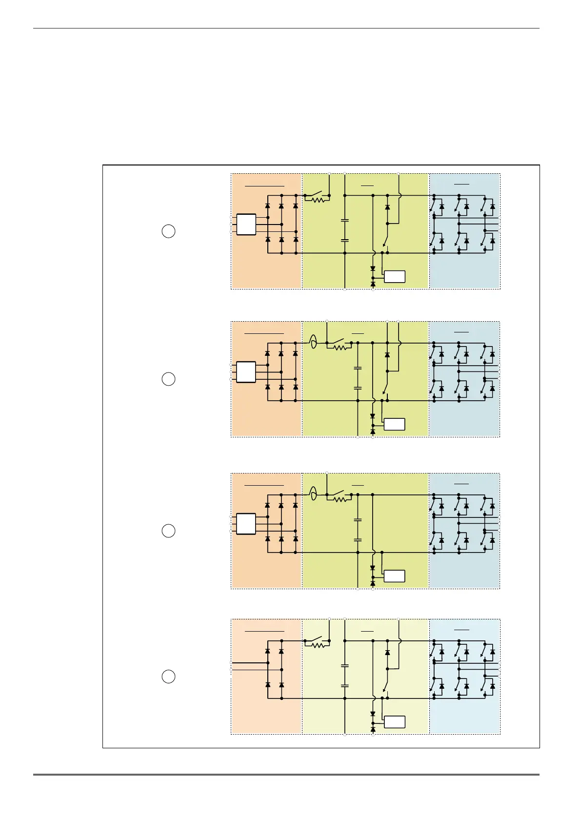
7.1.4 Block diagram of power section
This type is equipped with an EMI input lter (models ADL300.-...-F-..; except ADL300-...-2M), an AC/DC converter, a
system for pre-loading DC capacitors, a DC/AC converter, a power supply unit and an integrated braking unit.
To manage emergency situations (drive power failure) the unit also envisages connection of an emergency unit
between terminals EM and D.
A specic external resistor must be connected to perform the braking function.
The connection of the external braking resistor depends on the drive size:
• (1) (4) connect the resistor between terminals C and BR
• (2) connect the resistor between terminals BR1 and BR2.
• (3) an optional external BUy braking unit can be used and connected to terminals Cand D. Refer to the BUy hand-
book for further information.
EMI
L1
L2
L3
Emifilter & converter
DC link
Inverter
Rprc
SMPS
EMI
L1
L2
L3
Emifilter & converter
DC link
Inverter
Rprc
SMPS
C1 CBR
DEM
DEM
C BR1 BR2
U
V
W
U
V
W
ADL.-1040...3220-4
ADL.- -44300...5550
EMI
L1
L2
L3
Emifilter & converter
DC link
Inverter
Rprc
SMPS
DEM
C
U
V
W
ADL.-
ADL.-5370-2T
5750-4
L1
L2
Emifilter & converter
DC link
Inverter
Rprc
SMPS
C1 CBR
DEM
U
V
W
ADL.-1011...3055-2M
ADL.-2055...3110-2T
ADL.- -2T4150...5300
1
2
3
4
Filter (*)
Filter (*)
Filter (*)
(*) ADL300.-...-F-.. models
(*) ADL300.-...-F-.. models
(*) ADL300.-...-F-.. models

 Loading...


