66 ADL300 • Quick installation guide - Specifications and connection
8. Use of the keypad
This chapter describes the integrated keypad and the optional KB-ADL keypad and methods of use for displaying and
programming inverter parameters.
8.1 Description of keypads
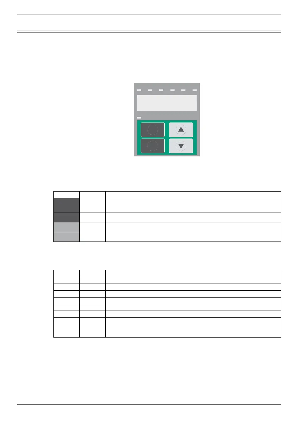
8.1.1 KB-ADL300 integrated keypad
→
Drive status indicator LEDs
→
Prg
Enter
BRK n=0ILIMENCNT AL
CAN
←
LCD display (4 characters + sign)
→
Membrane keypad
The integrated programming keypad is used to display status and diagnostics parameters during operation.
8.1.1.1 Membrane keypad
This section describes the keys on the membrane keypad and their functions
Symbol Reference Description
Prg
Returns to the higher level menu or submenu.
Exits a parameter, and a list of parameters.
It can be used to exit an error or alarm message.
Enter Enter
Enters the submenu or selected parameter, or selects an operation.
It is used when modifying parameters to confirm the new value that has been set.
Up
Moves the selection up in a menu or list of parameters.
During modification of a parameter, increases the value of the digit under the cursor.
Down
Moves the selection down in a menu or list of parameters.
During modification of a parameter, decreases the value of the digit under the cursor.
8.1.1.2 Meaning of LEDs
There are 7 drive status indicator LEDs on the front of the ADL300 drive.
LEDs Colour Meaning of LEDs
BRK Yellow The LED is lit when the drive has activated the brake release command
CNT Yellow The LED is lit when the drive has activated the close contactors command
EN Green The LED is lit during IGBT modulation (drive operating)
ILIM Red When this LED is lit the drive has reached a current limit condition. During normal functioning, this LED is off.
N=0 Yellow The LED is lit when motor speed is 0.
AL Red The LED is lit when the drive signals that an alarm has been triggered
CAN Green The LED is only present in types ADL300.-...-C.
LED flashes = pre-operational.
LED stays on = operational.
LED off = Stop.

 Loading...


