52 ADL300 • Quick installation guide - Specifications and connection
7.3 Connection diagrams
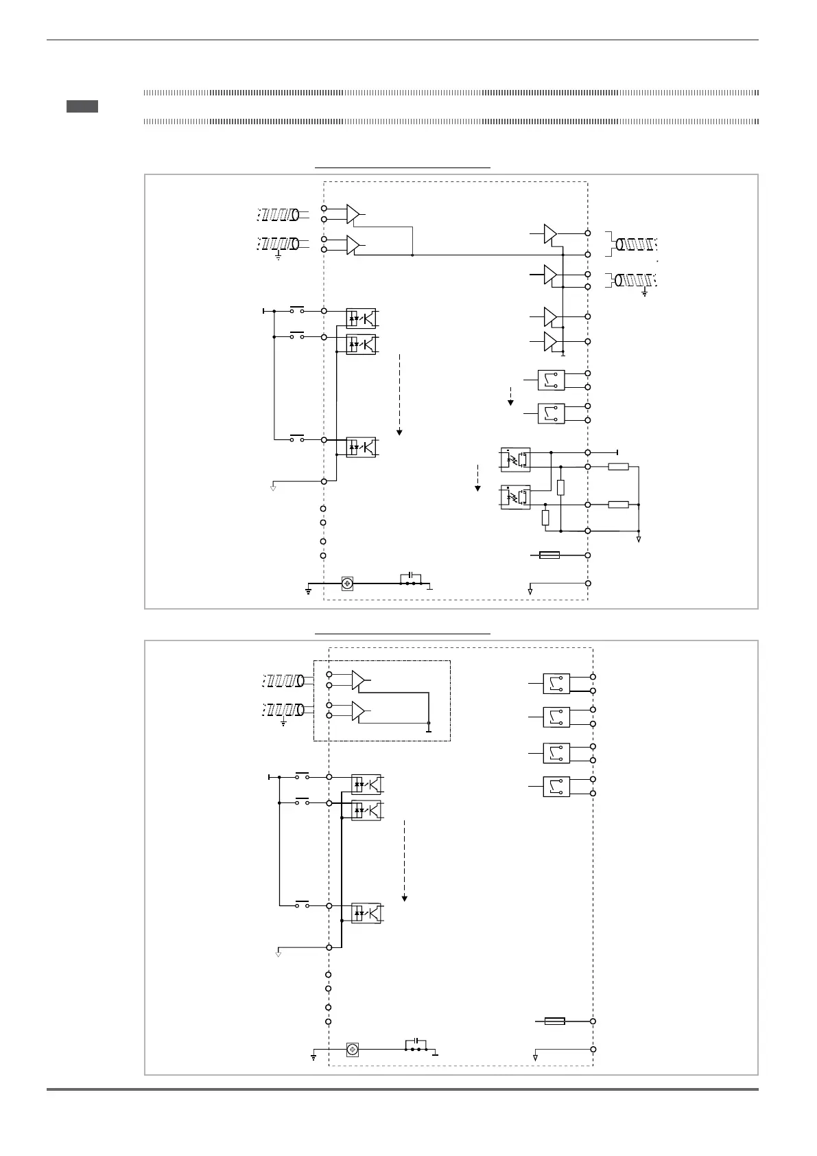
Note! This chapter describes the typical wiring diagrams with reference to ADL300 drives with standard configuration.
7.3.1 Regulation potentials, digital I/O
Figure 7.3.1.1: Regulation potentials (ADL300A)
Shielded cable
Chassis
0V
56
27
0V(+24V)
LOAD
+24V
0V(+24V)
LOAD
DO CM
Analog input 1
Analog input 2
Analog output 2
(Relay1)
(Relay n)
Digital Output 1
Analog output 1
HW Enable
Digital input 1
Digital input n
Digital Output n
57
47
45
-10V out
+10V out
43
42
41
40
9
8
DI COM
n
n
n
n
Shielded cable
+24V
Chassis
46
44
49
48
Chassis
29 DO-PS
28
10
SAFETY EN+
SAFETY EN-
SAFETY OK1
SAFETY OK2
+24V_OUT
0V (24V)_OUT
Isolated power supply
for Inputs/Outputs
Resettable fuse
12
11
Figure 7.3.1.2: Regulation potentials (ADL300B)
Shielded cable
Chassis
+24V_OUT
0V (24V)_OUT
0V(+24V)
Isolated power supply
for Inputs/Outputs
HW Enable
Digital input 1
Digital input n
9
8
DI COM
Resettable fuse
n
+24V
Chassis
12
11
10
57
Relay 1
Relay 2
56
Relay 3
Relay 4
55
54
53
52
51
50
Analog input 1
43
42
41
40
ADL300B-...-CN1
Analog input 2
SAFETY EN+
SAFETY EN-
SAFETY OK1
SAFETY OK2

 Loading...


