ADL300 • Quick installation guide - Specifications and connection 19
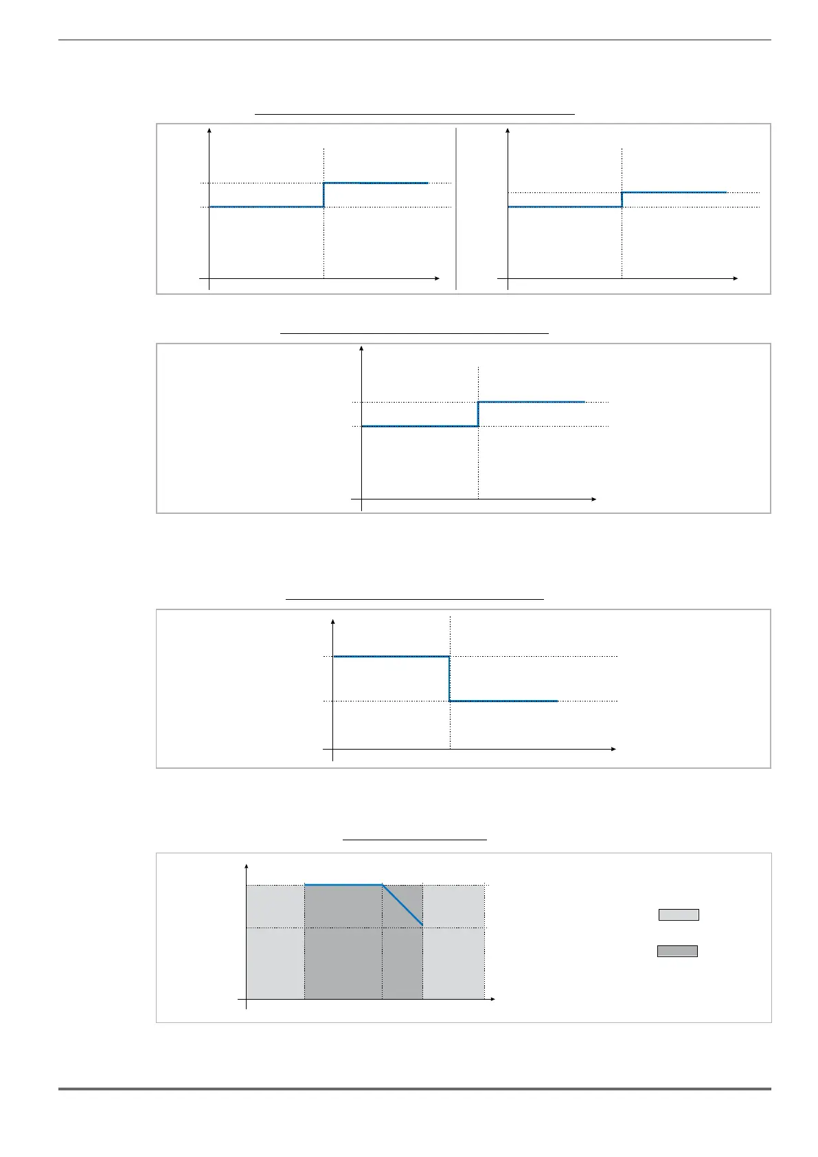
4.5.1 Derating values in overload condition
In overload conditions the output current depends on the output frequency, as shown in the gure below.
Figure 4.5.1-A: Ratio between overload/output frequency (ADL300-...-4 - ADL300-...-2T)
150
200
F out (Hz)
OL (% I)
N
3
150
180
F out (Hz)
OL (% I)
N
3
Sizes 1...3 (4...22kW) Sizes 4-5 (30...75kW)
Figure 4.5.1-B: Ratio between overload/output frequency (ADL300-...-2M)
150
200
F out (Hz)
OL (% I)
N
4.5.2 Derating values for switching frequency
The switching frequency is modied according to the temperature of the drive (measured on the heat sink), as shown in
the gure below.
Figure 4.5.2: Ratio between switching frequency/heat sink temperature
5
10
T diss (°C)
F (kHz)
SW
T diss th
4.5.3 Kalt: Ambient temperature reduction factor
Figure 4.5.3: Tamb reduction coefcient
Ta
T
-10 45 50
Function not allowed
Range of ambient temperatures allowed

 Loading...


