114 ADL300 • Quick installation guide - Specifications and connection
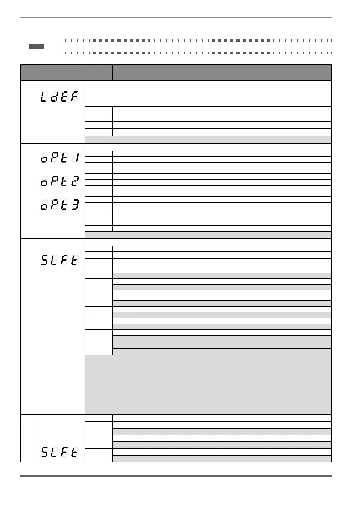
10.3 Messages
Note ! For more information see chapter 8.7.
Index Error message shown on
the display [on the inte-
grated keypad]
Sub-code Description
1
Load default param [LDEF]
Condition: may occur during loading of the parameter database saved in flash
normally appears in the following conditions: at initial power-on when a new firmware version is downloaded, when the regulation is installed on a new
size, when the region is changed.
If this message is displayed when the drive is already operating, this means that a problem has occurred in the parameter database saved in Flash.
If this message is displayed, the drive automatically performs the Load default command.
0001H-1 The database saved is not valid
0002H-2 The database saved is not compatible
0003H-3 The database saved refers to a different size from the current size
0004H-4 The database saved refers to a different region from the current region
Solution: Set the parameters to the value required and perform Save parameter
2
Option detect slot 1 [OPT1]
Option detect slot 2 [OPT2]
Option detect slot 3 [OPT3]
Condition: when the drive is turned on it recognises the presence of an optional card. One of the messages is shown on the display for a few seconds
0H-0 None
0004H-4 Can
0008H-8 Enc 1 EXP-DE-I1R1F2-ADL
3 0108H-264 Enc 2 EXP-SE-I1R1F2-ADL
0208H-520 Enc 3 EXP-SESC- I1R1F2-ADL
0308H-776 Enc 4 EXP-EN/SSI- I1R1F2-ADL
4 0408H-1032 Enc 5 EXP-HIP- I1R1F2-ADL
0101H-257 I/O 1 EXP-IO-D4-ADL
0501H-1281 I/O 1 EXP-IO-D8R4-ADL
0901H-2305 I/O 1 EXP-IO-D16R4-ADL
0F01-3841 I/O 1 EXP-IO-D12A2R4-ADL
1301H-4865 I/O 1 EXP-IO-D8A4R4-ADL
1501H-5377 I/O 1 EXP-IO-D6R2-F-ADL
00FFH-255 Unknown
Solution:
5 Autotune (motor) Condition: this may occur during the self-tuning procedure
[SLFT] 0 No error
1 N.A.
2 N.A.
3
The motor plate data parameters have changed but the Take parameters command, PAR 2020, has not been executed
Solution: Execute the Take parameters command.
4
The motor is not connected
Solution: Connect the motor
5
While running self-tuning the ESC key was pressed or the enable contact was opened or an alarm occurred. The self-tuning command
was sent with the drive in the alarm condition
Solution: Eliminate the reason for the alarm, remove the reason for the opening of the enable contact, reset alarms.
6
A setting performed by the self-tuning function produced a parameter value outside the min or max range.
Solution: Check the motor plate data or drive and motor sizes have been combined incorrectly.
7
The self-tuning command was sent without being enabled.
Solution: Close the enable contact before sending the self-tuning command
8 ... 21
A setting performed by self-tuning has reached a measurement method limit
Solution: Check the motor plate data or the drive and motor sizes have been combined incorrectly.
30
The Enable was not given or removed in time during the phasing procedure.
Solution: Repeat the phasing procedure and check the connection of the enable signals.
Solution: If the message appears with a value other than 0, follow the instructions supplied for each particular case and repeat self-tuning. This should
be performed using the wizard function available from the keypad (STARTUP WIZARD) and the Tool software on the PC.
Pay attention to all motor plate data parmaeters, especially:
- Rated speed, Motor rated speed in rpm.
• (ADL300 for Asynchronous motor) Take care not to set the Rated speed parameter to the synchronous speed. The value of the Rated speed
parameter must be less than: [(Rated frequency * 60) / Pole pairs].
• (ADL300 for Synchronous motor) Take care to set the Rated speed parameter to the synchronous speed.
- Rated frequency, Motor rated frequency in Hz
- Pole pairs, Motor pole pairs
If the problem persists even after following the instructions supplied, confirm the values of the motor plate data parameters, execute the Take param-
eters command but not self-tuning.
5 Autotune 0 No error
(phasing)
40
The encoder card in use cannot manage automatic phasing.
(Only Synchronous) Solution: Use the appropriate encoder card
[SLFT]
41
Incorrect Incremental encoder impulse count
Solution: Check the electric signals of the incremental encoder. Check the value of the encoder impulse parameter
42
Incorrect absolute encoder impulse count
Solution: Check the electric signals of the absolute encoder. Check the configuration of the absolute encoder

 Loading...


