ADL300 • Quick installation guide - Specifications and connection 47
(3) Connection EnDat Encoder + 2 Freeze (EnDat-SSi)
Technical specication:
Channels ������������������������������� A+ A-, B+ B-, differential
Management of loss of encoder signals.
Max frequency �������������������������� 200 kHz (check the number of encoder impulses according to the maximum speed)
Number of impulses ���������������������� min 128, max 16384 (automatic recognition at initialisation)
Electrical interface ������������������������ 0.6 V ≤ Vpp ≥ 1.2 V (typ. 1.0 V)
Load capacity ��������������������������� 8 mA @ 1.0 Vpp (Zin 120Ω)
Programmable internal power supply ���������� min +5.2 V, max +6.1 V (default + 5.2 V) − Imax 150 mA.
The internal power supply of the encoder can be selected from the keypad (ENCODER CONFIG
menu, parameter Encoder supply (PAR 2102) to balance the loss of voltage due to the length of
the encoder cable and load current.
PAR 2102 Encoder supply range: min=5.2V, max= 6.1V, step of 0.1V; default=5,2V.
The encoder supply voltage will be rounded off to the nearest value among those 4 values avail-
able via hw: 5.2V / 5.5V / 5.8V / 6.1V.
Cable length ���������������������������� max 50m (see encoder cable length section)
Absolute channels ������������������������ CK+ CK-, DT+ DT- differential, RS-485
Management of loss of encoder signals.
Interface ������������������������������� EnDat: 2.1/2.2 single/multi-turn (command set managed only compatible with 2.1)
SSI: Standard Sick/Stegman single/multi-turn
Max frequency �������������������������� EnDat: 1 MHz with delay compensation (not programmable)
SSI: 400 KHz (not programmable)
Number of bits ��������������������������� EnDat: max 32 bit/turn* max 32bit/turn (automatic recognition at initialisation)
SSI:13-25 bits (default 25)
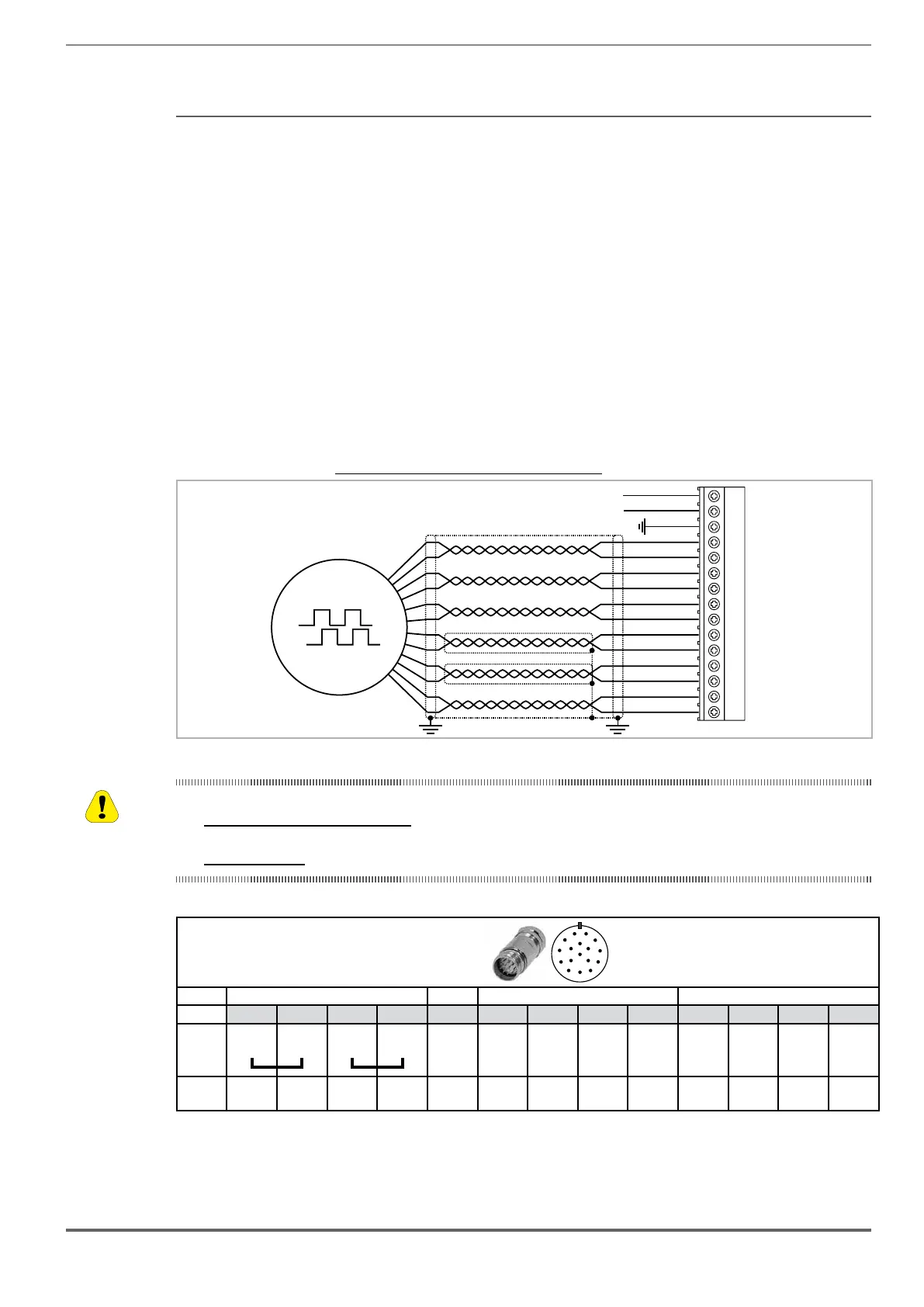
Figure 7.2.7: Connection EnDat Encoder + 2 Freeze (EnDat-SSi)
DT-
DT+
CK-
CK+
A-
A+
0VE out
+VE out
VS-
VS+
B-
B+
8
9
10
11
12
13
14
15
1
2
3
4
5
6
7
(*)
(**)
(**)
Fast input 2
Fast input 1
CM
XE
(*) Connection of shielding, see gure 7.2.4
(**) Caution - If not strictly observed, could result in damage to or destruction of encoder!
• ADL300B-...-...-F-4-C - E24I models: do no connect SENSOR-0V (VS- XE.8) and SENSOR-Up (VS+ XE.9).Based on
standard cable do not use PIN 1 and PIN 4
• All other models: VS+ / VS- : optional (encoder power supply feedback)
Typical connection with M23 17 pin connector
on motor side.
1
2
3
4
5
6
7
8
9
10
11
12
1316
14
15
17
Power supply Incremental Signal Absolute position values
Pins 7 1 10 4 11 15 16 12 13 14 17 8 9
Up
Sensor
Up
0V
Sensor
0V
Inside
shield
A+ A - B+ B- DATA
____
DATA
CLOCK
____
CLOCK
Cable
Colour
Brown
/ Green
Blue
White /
Green
White -
Green /
Black
Yellow /
Black
Blue /
Black
Red /
Black
Gray Pink Violet Yellow
* Optional.

 Loading...


