58 ADL300 • Quick installation guide - Specifications and connection
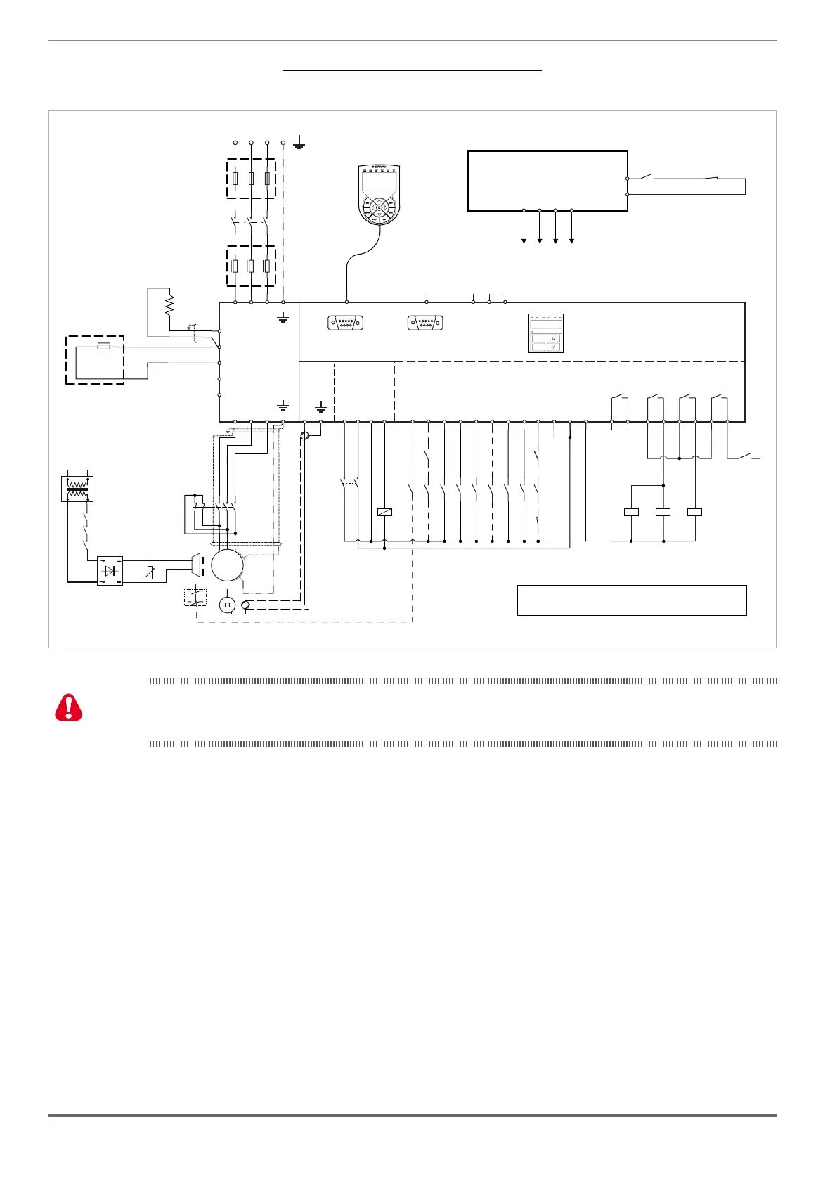
Figure 7.3.2.7: Safety connections for control using a single contactor
Diagram of a lift system complying with EN81-1 12.7.3 b), with just one contactor and integrated safety function.
AC
L1
1
2
K1M
3
4
5
6
F1
M
3
~
DC
L1
ADL300.-...-4 (size 1, 2 and 3)
U1
V1 W1
U2
V2
W2
P-ADL
EXP-IO
R-ADL
RS232
DI8
DI7
DI6
DI5
DI4
DI3
DI2
DI1
ENHW
DICM
0VOUT
24VOUT
L1 L2 L3
KEYPAD / DCP
PC
T1 T2 T3
123456789101112
PE
PE
50
51
D
C1
BR
EM
OPTIONAL
BrakeFbk
MltSpd S1
MltSpd S2
Emergency mode
MltSpd S0
StartFwdCmd
StartRevCmd
Safety
chain
OPTIONAL
BREAKING
RESISTORS
C
BRAKE
CONTACTOR
OK
DRIVE
52
53
54
55
CONTACTOR
RUN
56
57
L1
A1
A2
A1
A2
A1
A2
K2M
K3M BR
BRAKE
K2M
K3M
BR
TRAFO
3 Phase Mains
FBR
5
6
3
4
1
2
K3M
Emergency
Failure
(optional)
SAFETY EN+
SAFETY EN-
SAFETY OK1
SAFETY OK2
EXP-ENC
PE
CAN
SH
H
L
Prg
Enter
BRK n=0ILIMENCNT AL
CAN
Internal Keypad
SYSTEM CONTROL UNIT
Commands
Contactor
check-up
K4
K3M
K4
Safety
chain
K2M
K2M
K3M
K4
K3M
(*): and must be checked by control unitK4 K3M
To use this type of connection reference should be made to the safety and installation instructions in the "SAFETY
MANUAL" (le: x08051ko-Safety User Manual-1_0r_IT and x08051ko-Safety User Manual-1_0r_EN on the CD-ROM
supplied with the inverter or downloadable from the www.gefran.com website).

 Loading...


