6-8 RADIO CONFIGURATION
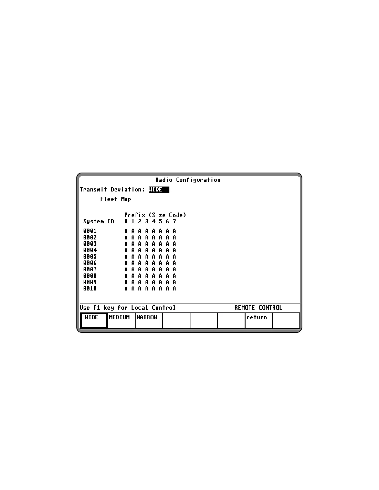
Data displayed on the Radio Configuration screen
depends on the signaling type. The values for
Control Channel Transmit Deviation, the
SMARTZONE Connect Tone, and the Trunk I,
Trunk I EP II fleet maps are entered through this
screen.
6-8.1 Radio Configuration Trunk I
and Trunk I EP II
The Trunk I and Trunk I EP II Radio Configuration
Screen allows the fleet map of the
radio being tested and the transmit deviation level
for the control channel to be entered. Ten
system/fleet map configurations can be stored in
the analyzer.
With the Trunk mode activated per paragraph 6-5,
place the cursor in the "Sig Type:" field and press
the softkey TRUNK I (or TRUNK I EP II) to select the
desired signaling. Place the cursor in the "Meter:"
field and press the softkey
RADIO CONFIG. A
screen similar to figure 6-9 appears.
Figure 6-9. Radio Configuration Screen – Trunk I and Trunk I EP II
With the above screen displayed, use the cursor
control keys to position the cursor, and the softkeys
to select the following parameters:
Transmit Deviation:
The Transmit Deviation selection allows for the
selection of either wide, medium, or narrow FM
deviation selections per table 6-5.
103
 Loading...