Mon RF In
Selects the RF input port via softkeys. The
RF I/O port contains an RF load and
should be used for direct connection to the
radio under test. The ANT port accesses
the unit's sensitive receiver and should be
used with an antenna for "off-the-air"
reception. Selection of the ANT port is
indicated by a red LED next to the ANT
connector.
CAUTION
Do not apply input power to the ANT input
port. In the event RF power is inadvertently
applied, the port is protected by an in-line RF
fuse. This fuse may be accessed by unscrewing
the front of the BNC connector out of the front
panel.
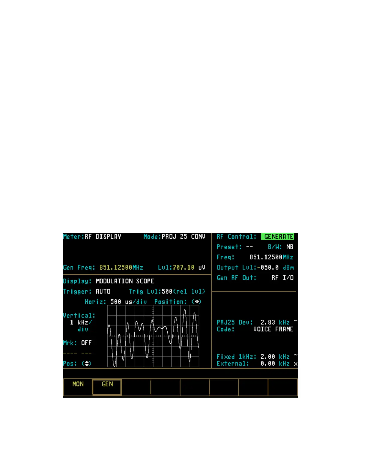
21-8.2 GENERATE Mode
The GENERATE mode (Figure 21-12)
configures the Analyzer to generate an RF
signal at a controlled output level. The
GENERATE m
ode thus provides for Project
25 radio receiver testing. In PROJ 25 CONV
Generate mode, the RF Zone is similar to the
RF Zone in standard mode. It is capable of
setting up the analyzer to generate RF output
through its RF I/O port or through the
Generator Output (GEN OUT) port. The RF
Zone contains fields for choosing the generator
bandwidth, frequency, output level, and output
connector of the Project 25 RF signal. All of
these fields operate as described under the
General Operations tab in this manual except
the “Modulation Type:” field is not required.
Specific controls that further configure the
GENERATE mode are located in RF Zone
when GENERATE is first selected.
Figure 21-12. Generate Mode - RF Zone
268
 Loading...