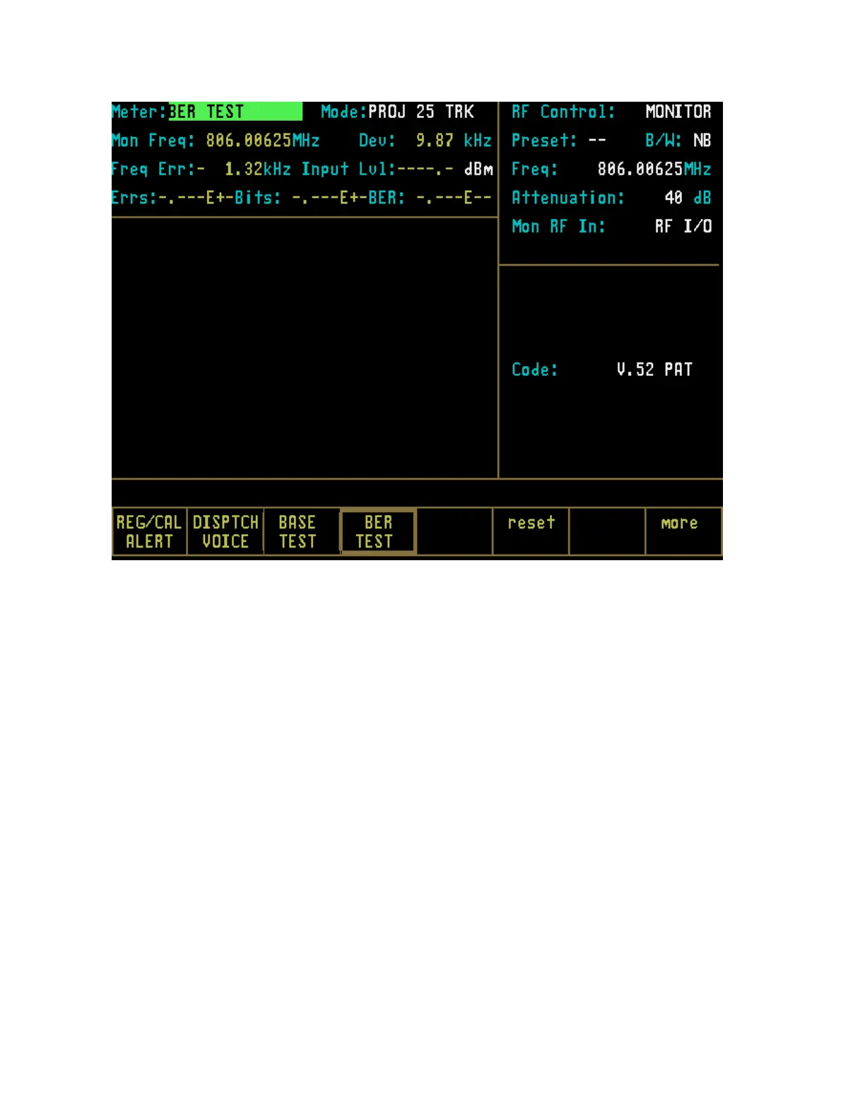
Figure 24-7. PROJ 25 Trunk BER test Meter Selection
24-5 TEST SETUP
24-5.1 Connecting a Radio
Use a 50-ohm BNC cable and an N to BNC
adapter to connect from the RF I/O port of
the R2670 or R2625 analyzer to the antenna
port of the radio as shown in figure 24-8.
CAUTION
When in Monitor mode, adjust the squelch
to where the LED indicator for squelch
turns off or is closed. When the signal from
the radio is present, the squelch LED will
illuminate, indicating that squelch has
been detected and there is a signal present
CAUTION.
Observe the input power ratings and
warnings of the analyzer to insure that no
damage occurs to the analyzer
304
 Loading...