9
7. Insert the whip antenna into the ANT port,
located to the right of the tuning knob on the
front panel.
1-6.3 Battery Pack Operation
The optional battery pack (R
PN-4000A) is
designed to conveniently mount to the back of the
Analyzer. Containing an internal battery charger,
the battery pack is automatically recharged
whenever connected direct to an ac receptacle.
Battery charging is independent of the main
equipment.
8.
Press the power switch ON. The Analyzer is
now ready for use. Before operating the
Analyzer, review the operating procedures
described in this manual.
CAUTION
NOTE
When installing the Analyzer in a vehicle, fuse
the DC supply line close to the vehicle's
battery. The DC-10A fuse (located on the
Analyzer's rear panel) protects the Analyzer
against overload but does not protect the
vehicle.
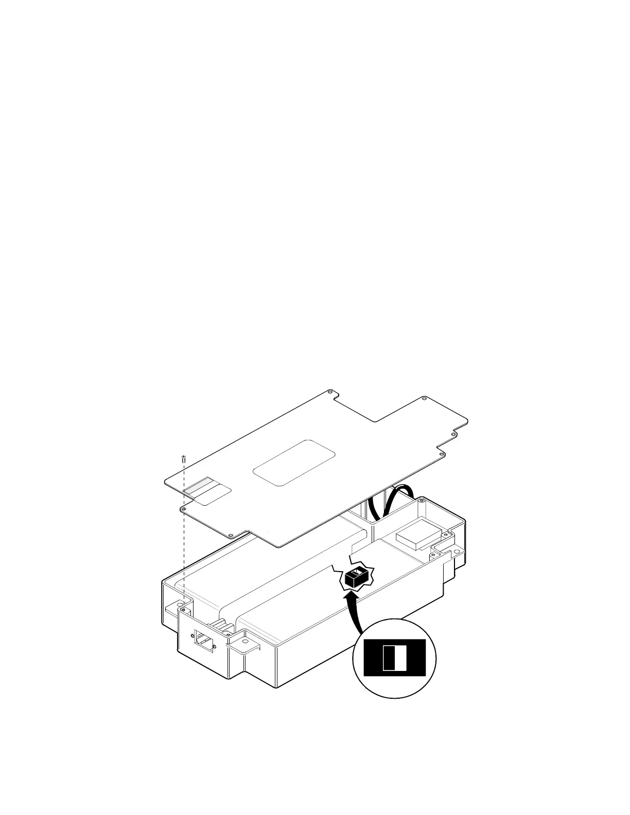
The battery pack has an internal switch
allowing the user to switch operation of the
battery pack to 115 VAC or 230 VAC. Before
attempting to plug the battery pack into the ac
line for charging, ensure this switch is set to
the correct position for your line voltage. This
switch is accessib
le by removing six screws
attaching the cover to battery pack chassis as
shown in figure 1-1.
1
1
5
V
1100-1
Figure 1-1. 115 VAC/230 VAC Selection Switch
 Loading...