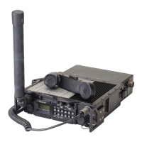
General Dynamics C4 Systems URC-200 (V2)
99
CAUTION
DO NOT install the LOS antenna on the transceiver during testing in the
transmit mode with (1) the cover removed or (2) the transceiver powered from
an external power supply via test leads that are unshielded. RF from the
antenna can radiate into the transceiver, circumvent the protection loops, and
cause severe damage to the transmitter circuits.
5.3.3.1 Frequency Accuracy and FM Power Output
NOTE
If the frequency accuracy measurement fails refer to Appendix A for
crystal warp adjustment procedures. This procedure only applies to
transceivers with software version 1.6 and later. For radios with older
software please contact General Dynamics Customer Support.
1. Set up the test equipment as shown in Figure 17. Connect the
VERT/SINAD/DIST/DVM/COUNTER IN connector to the DEMOD connector on the
R2600. For now, do not connect the R2600 MOD OUT port to either pins B or H of the
Remote connector on the URC-200 (V2). Also for now, do not connect the PTT (Push-to-
Talk) line (pin F) to ground.
NOTE
When the PTT line is grounded the URC-200 (V2) transmitter is keyed and
begins transmitting.
2. Set the input power supply to 28 ±1 VDC.

 Loading...