| CARDIOHELP System | 6 Repair | 121 |
Service Manual | 3.3 | EN | 05
Copyright Maquet Cardiopulmonary GmbH
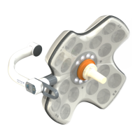
6 Remove all plugs from HMI PCB.
HMI PCB
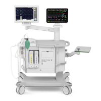
7 Remove sealing from connector X13.
8 Unscrew the 6 marked (blue) screws.
9 Unscrew the 3 marked (red) hex nuts of HMI PCB
10 Remove the HMI PCB and place it on the ESD workstation.
HMI PCB
NOTE
Perform necessary steps of service work.
▶ Additional steps could be:
- Replacement of the HMI PCB.
- Replacement of display and touchpanel (⇨ "Replacing Display and Touch Panel", page 122).
- Replacement of rotary encorder (⇨ "Replacing Rotary Encoder", page 126).
- Replacement of equipotential bonding pin (⇨ "Replacing Equipotential Bonding Pin", page 129).
CAUTION!
For replacing HMI PCB.
Remove SD-card and insert it into the new HMI PCB.
6.14.1 Assemble the HMI PCB
1 Preassemble the sealing plate for the HMI according to the drawing.
2 Attach a thin film of Hylomar sealant on the sheet metal side of the sealing plate.
3 Push the sealing plate for the HMI with the sheet metal side over the threaded welded bolts on the
socket plate.
4 Align the sealing plate at the socket openings.
5 Push the flexible part of the HMI board at the flexible conductor over the threaded welded bolts on the
sealing plate.
CAUTION!
Make sure that the sockets are aligned with the corresponding slots.
6 Fasten the board with 3.2 mm washers and M3 screws, with a torque of 0.5 Nm and Loctite 270, onto
the socket plate.
7 Mount the HMI PCB using 6 M2.5 screws marked (blue) with a torque o 0.3 Nm and Loctite 270.
 Loading...