Operation
Publication 21555, Rev. E, September 2002 2-57
Gain = 1, Amp 2:
1200
1000 950 1050 GAIN = 1, AMP 2
This test sets the sensor input amplifier offset
DAC to 1volt and measures the output of the
second stage amplifier with its gain set to 1. It
then compares the results with the limits shown to
the left and if outside any limit it will set the error
number corresponding to that voltage level. Then
it sets the gain of the second stage to 8 and
measures the output of that stage. Any out of
tolerance voltage will be indicated by a
corresponding error number. This checks the gain
of this stage at a gain of 8.
Gain = 8, Amp 2:
1201
8000 7200 8800
Gain = 1, Amp 2:
1400
100 90 110 GAIN = 1, AMP 2
This test sets the sensor input amplifier offset
DAC to 0.1volt and measures the output of the
second stage amplifier with its gain set to 1. It
then compares the results with the limits shown to
the left and if outside any limit it will set the error
number corresponding to that voltage level. Then
it sets the gain of the second stage to 64 and
measures the output of that stage. Any out of
tolerance voltage will be indicated by a
corresponding error number. This checks the gain
of the second stage at a gain of 64.
Gain = 64, Amp 2:
1401
6400 5760 7040
1600 9000 8000 10000 TOO HIGH
This test checks the upper limit for the auto-range
system by applying a voltage from the offset DAC.
The output of the second stage is monitored while
also monitoring the ! too-high comparator output.
If the comparator output comes true outside of the
voltage limits specified to the left the
corresponding error number is set.
1800 1000 700 1100 TOO LOW
This test checks the lower limit for the auto-range
system by applying a voltage from the offset DAC.
The output of the second stage is monitored while
also monitoring the ! too-low comparator output. If
the comparator output comes true outside of the
voltage limits specified to the left the
corresponding error number is set.
2000 7000 6300 7700 CAL HEATER
This measures the calibrator thermistor heater
voltage. This is half of the actual voltage on the
heater transistor collector which will be about
0.5volts below the level of the 15volt supply after
the heater is stable. Since this takes about a
minute after power on the POST does not check
this. However the command *TST? does.
2100 0 0 500 SW +5 OFF
This test measures the switched 5volt logic
supply applied to the sensor when it is switched
off. Whenever a peak power sensor (8034X or
8035XA) is connected, this test will be bypassed.
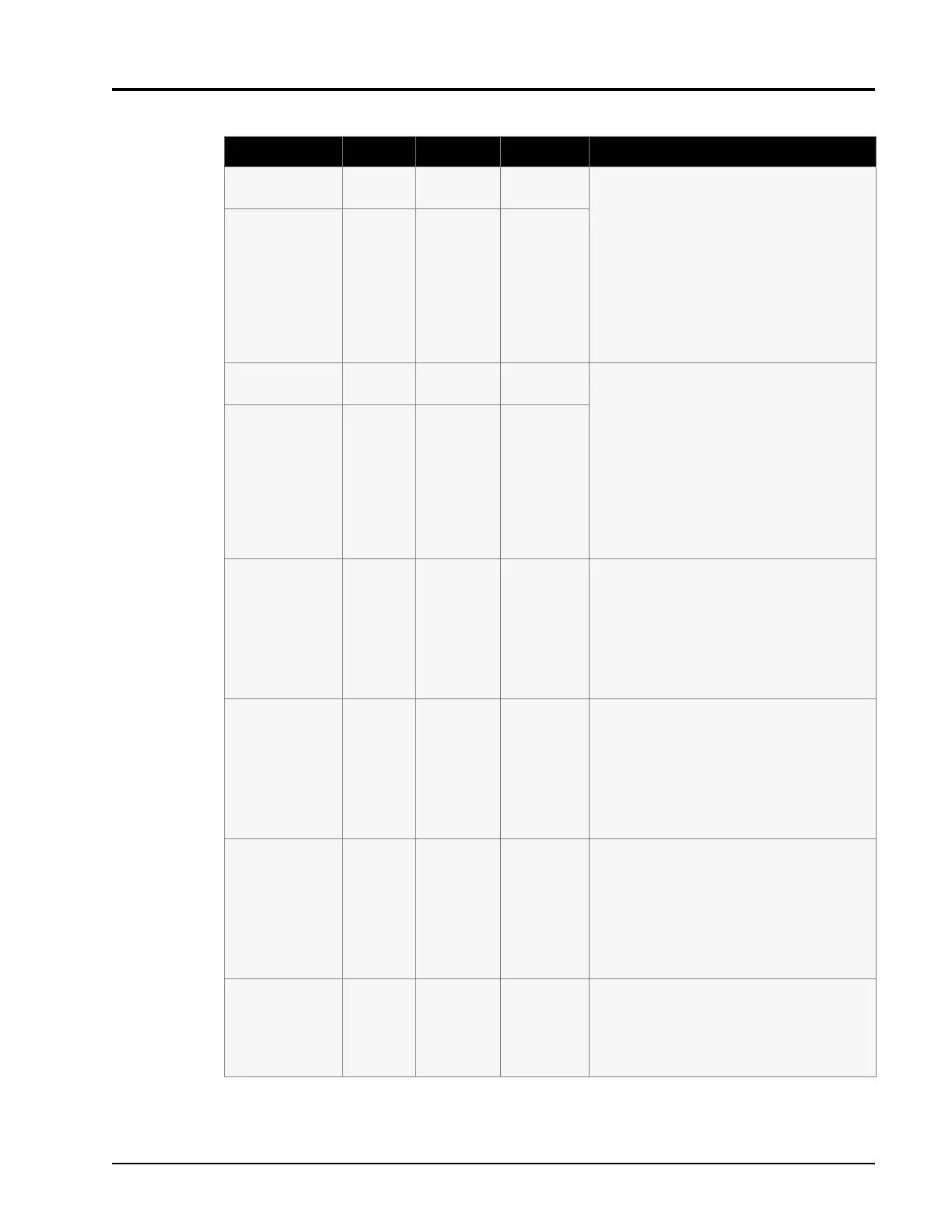
Table 2-5: Self-Test Error Indication & Limitations (Continued)
Error Number Result Minimum Maximum Test Description