82 Detail program description - Base setup models | Winged models
the original value.
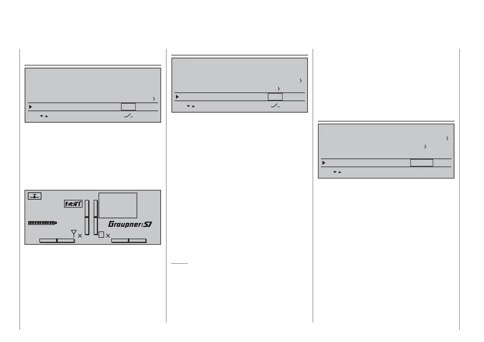
Power-on warning
BASIC SETTING,MODEL
SET SET
RF range test 99s
DSC Output PPM10
Motor Stop +100%
–125%
8
Thr. CutOff
–––
When a switch, a control switch or a logical switch
is assigned in this line as described in the section
"Assigning transmitter controls, switches and control
switches" on page 56, the respective switch or control
position will be polled and an appropriate warning
will be blended into the basic display under some
conditions. In combination with logical switches,
almost any switch setting can be called up for
transmitter switch on.
#01
0:00h
Stoppuhr
Flugzeit
K78
0:00.0
4.1V
0:00.0
00
0
0
00:00h
M
V
!Warning!
Graubele
H-J Sandbrunner
Auto trim
BASIC SETTING,MODEL
SET SET
DSC Output PPM10
Thr. CutOff +100%
–125%
8
Power on warning
L1
Auto trim –––
The "Auto trim" option makes it possible to trim a
model quickly and without complications, e.g. in the
context of a fi rst-fl ight or even after (major) repairs, etc.
Typically such test fl ights are initially fl own with joysticks
counter operated until the desired state of fl ight is
achieved. This generally involves working the trim
controls during the fl ight to "unburden" the joysticks.
This is exactly what the "Auto trim" function is for.
After the desired fl ight attitude has been achieved
via control functions 2 … 4 (aileron, elevator and
rudder), the switch assigned to "Auto trim" – ideally
one of the standard-equipment momentary switches
in the switch panels – is to be activated ONCE. At the
instant the switch is activated, the joystick offsets from
their neutral positions will be determined and adopted
as trim values. However, this does not take place
instantaneously but rather within about 1 second.
During this period after the switch has been activated,
the joysticks should be returned to their normal
positions.
Notes:
Due to the complex interaction inherent to multi-•
fl ap models, the Auto trim function for ailerons
is deactivated if "2AIL 2FL" and "2AIL 4FL" or
"4AIL 2FL" and "4AIL 4FL" is selected in the
"Aileron/camber fl aps" line of the »Model type«
menu.
Be sure that during the switch assignment, the •
joysticks for aileron, elevator and rudder are in
their neutral positions as otherwise their offsets
from neutral will be adopted right away in trim
memory as the trim value.
Since EVERY activation of the Auto trim switch •
has a cumulative effect, after concluding an "auto
trim" fl ight, the assigned auto trim switch should
be deactivated for reasons of safety. Otherwise
there is a residual danger that the "Auto trim"
function could be activated accidentally.
ext. PPM signal
BASIC SETTING,MODEL
SET SET
Thr. CutOff +100%–125%
8
Power on warning L1
Auto trim –––
ext. PPM signal normal
SEL
Some RF modules which can be connected to the
external (page 25) or internal (page 26) connectors
for other RF modules require an inverted input signal.
Be sure to follow the respective module's installation
instructions for this.
The choice of "inverted" instead of the default preset
"normal" allows for appropriate adaptation of the
provided PPM signal.
A simultaneous tap on the cd or ef keys of the
right touch pad (CLEAR) will reset the display to
"normal".
 Loading...


