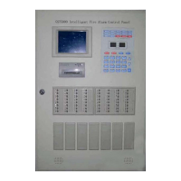
GST5000 Intelligent Fire Alarm Control Panel
Installation and Operation Manual (Generic Part)
The Intelligent Solution
Page 9
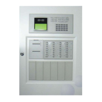
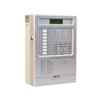
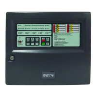
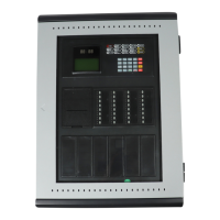
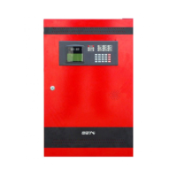
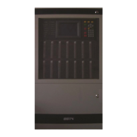
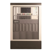
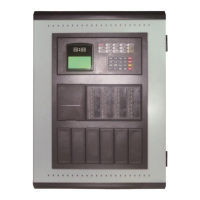
panel. Rack type and console type can be expanded with more on order.
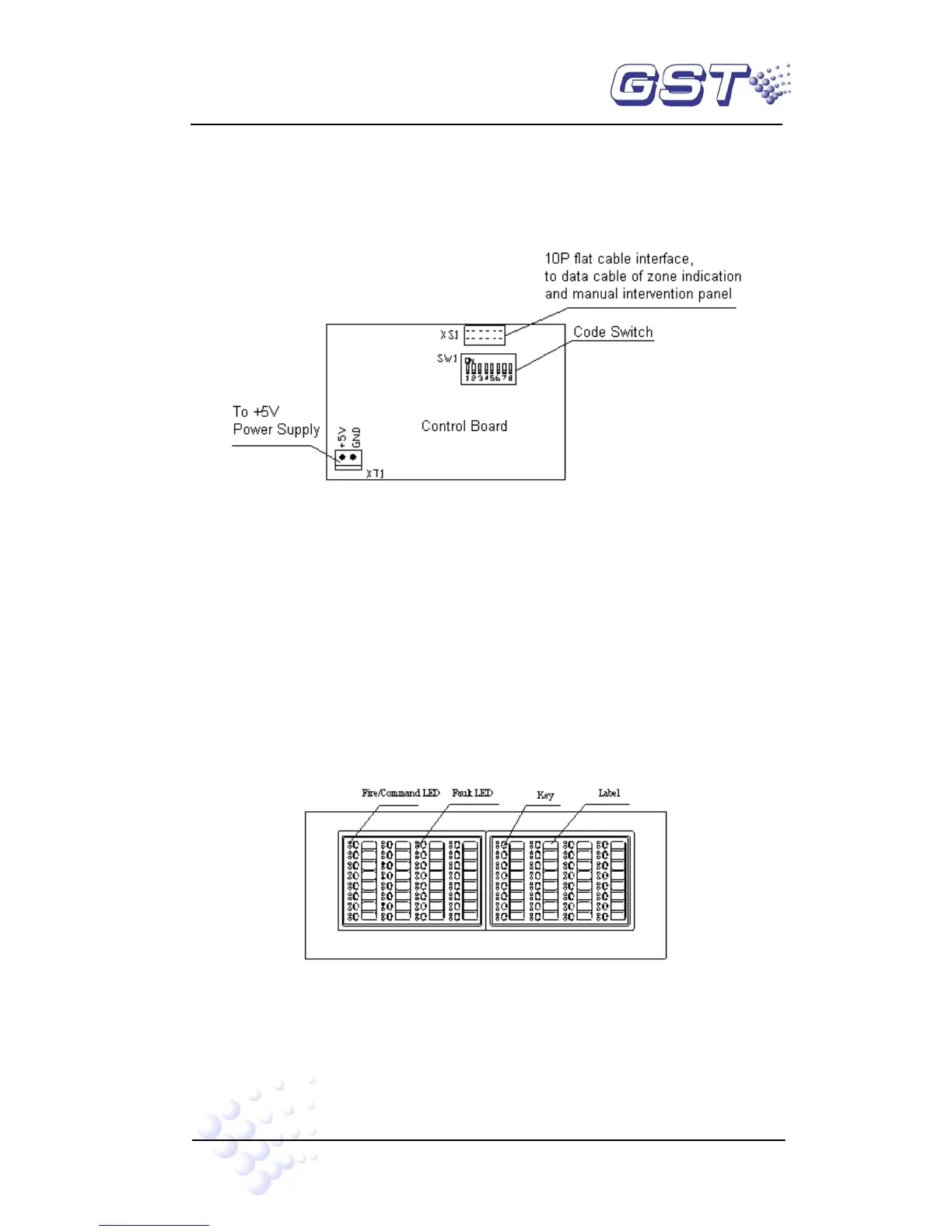
3.2.1 Structure
The ZCP includes two LED boards and one control board. Control board connects with
the two LED boards through pins. Structure of the control board is shown in Fig. 3-2.
Fig. 3-2
Every loop card can drive 4 ZCPs. All of them are connected together with a 10p ribbon
cable through XS1 of the control board.
We can use the switch to set a code for each ZCP.
z No. 1: 1, 6, 8 at ON, others at OFF.
z No. 2: 2, 6, 7 at ON, others at OFF.
z No. 3: 3, 5, 8 at ON, others at OFF.
z No. 4: 4, 5, 7 at ON, others at OFF.
3.2.2 Functions
Fig. 3-3
Each switch includes a red LED, a yellow LED, a key (which can directly initiate
connected devices) and a label (brief description of the start key).
The ZCP can be defined as three operation modes: