GST5000 Intelligent Fire Alarm Control Panel
Installation and Operation Manual (Generic Part)
The Intelligent Solution
Page 21
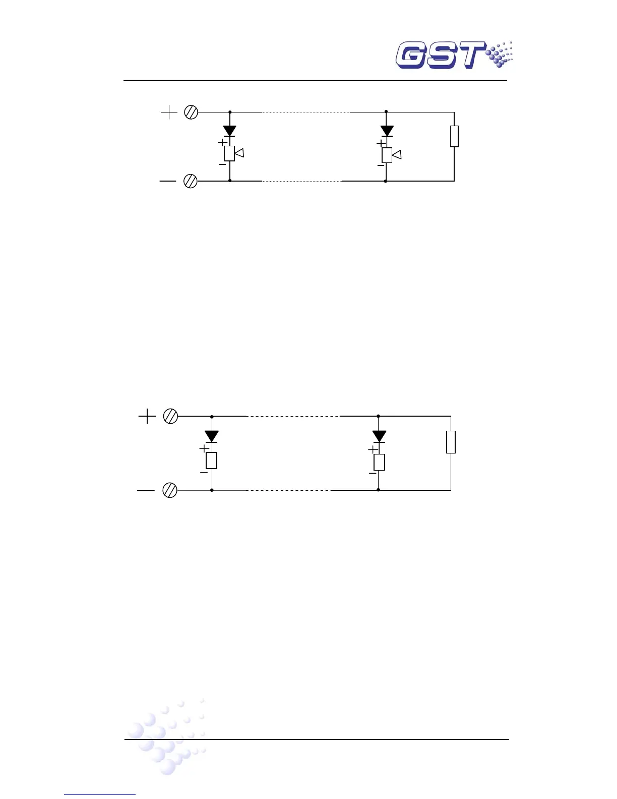
Fig. 4-4
Description:
A 4.7kΩ resistor is connected at the SOUNDER CIRCUIT OUTPUT as factory default.
Please remove it and keep it well before connection. After connecting the loop in correct
polarity, add the resistor to the end of the line
NOTE: The sounder strobes are polarized. Note polarity in connection. The
maximum current of the circuit depends on the number of sounder strobes. Do
not overload.
4.4.2 Connection of F.P.E. Output
F.P.E. output is shown in Fig. 4-5.
Fig. 4-5
A 4.7kΩ resistor is connected at the F.P.E. OUTPUT as factory default. Please remove
it and keep it well before connection. After connecting the loop in correct polarity, add
the resistor to the end of the line.
NOTE: F.P.Es are polarized. Note polarization in connection. The maximum
current of the circuit depends on the number of F.P.E. Do not overload.
4.4.3 Connection of Fire Alarm Output
Fire alarm output is shown in Fig. 4-6.
Sounder
Di