GST5000 Intelligent Fire Alarm Control Panel
Installation and Operation Manual (Generic Part)
The Intelligent Solution
Page I
CONTENTS
Chapter 1 Product Introduction ..................................................................................... 1
Chapter 2 Technical Specifications............................................................................... 2
2.1 Operating Voltage.................................................................................................... 2
2.2 Standby Batteries .................................................................................................... 2
2.3 Communication Loop Parameters ........................................................................... 2
2.3.1 RS485 Communication Loop ............................................................................ 2
2.3.2 RS232 Communication Loop ............................................................................ 2
2.4 Detection Loop Parameters..................................................................................... 2
2.5 Output Loop Parameters ......................................................................................... 3
2.6 Dimension................................................................................................................ 3
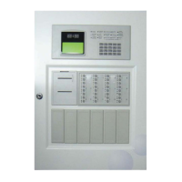
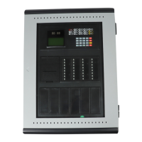
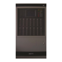
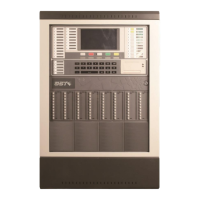
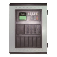
2.6.1 Wall-mounted GST5000W FACP...................................................................... 3
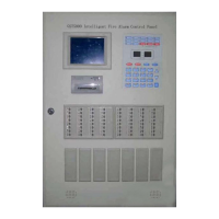
2.6.2 Rack type GST5000 FACP ............................................................................... 4
2.6.3 Console type GST5000 control panel ............................................................... 5
Chapter 3 Structure and Configuration......................................................................... 7
3.1 Display and Operation Area..................................................................................... 7
3.1.1 Indicators .......................................................................................................... 7
3.1.2 Key Functions ................................................................................................... 8
3.2 Zone Indication and Manual Intervention Panel (ZCP) ............................................ 8
3.2.1 Structure ........................................................................................................... 9
3.2.2 Functions .......................................................................................................... 9
3.3 Configuration ......................................................................................................... 10
3.3.1 Typical Configuration....................................................................................... 10
3.3.2 Optional Configuration .................................................................................... 14
3.4 Field Devices ......................................................................................................... 15
3.4.1 A Series of Intelligent Fire Detectors ............................................................... 15
3.4.2 Modules .......................................................................................................... 15
3.4.3 Loop Isolator ................................................................................................... 15
3.4.4 Manual Call Point............................................................................................ 15
3.4.5 Addressable Sounder Strobe .......................................................................... 16
3.4.6 GST852RP Repeater Panel............................................................................ 16
3.5 C&E Equation and Device Definition Software ...................................................... 16
Chapter 4 Mounting ...................................................................................................... 17
4.1 Configuration Inspection........................................................................................ 17
4.1.1 Check Engineering Configuration ................................................................... 17
4.1.2 Check Internal Configurations and Interconnection of the FACP .................... 17
4.2 Installation of the Cabinet ...................................................................................... 17
4.2.1 Installation condition and method of wall-mounted FACP ............................... 17
4.2.2 Installation condition and method of rack type and console-typed FACP. ....... 18
4.3 Start-up Check....................................................................................................... 18
4.4 Connections of Field Devices ................................................................................ 19
4.4.1 Connection of Sounder Circuit Output ............................................................ 20