GST5000 Intelligent Fire Alarm Control Panel
Installation and Operation Manual (Generic Part)
The Intelligent Solution
Page 60
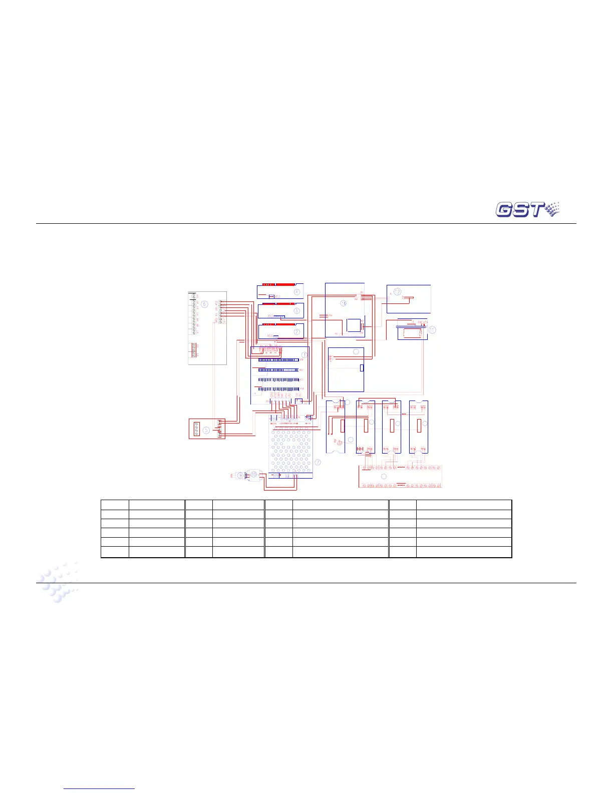
Appendix 1 Internal Connection Diagram
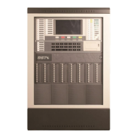
1. GST5000W Wall Mounted
Z1n-
ZI+
ZI-
ZO-
ZO+
XT3
XT4
24-
24+
24-
24+
XT2
XT1
Z1n+
F
.
P
.
E
O
U
T
P
U
T
C
L
A
S
S
C
H
A
N
G
E
F
A
U
L
T
O
U
T
P
U
T
N
C
C
O
M
N
O
S
O
U
N
D
E
R
C
I
R
C
U
I
T
P
O
U
T
P
U
T
-
+
N
E
T
W
O
R
K
B
A
F
I
R
E
A
L
A
R
M
O
U
T
P
U
T
-
+
-
+
L
O
O
P
O
U
T
-
+
L
O
O
P
I
N
+
-
L
O
O
P
B
U
S
R
E
P
E
A
T
E
R
B
A
R
S
-
4
8
5
C11+
C3-
C1-
C1+
C3+C2+
C2-
C4-
C4+
8
100W Power Supply
to main board
to Loop Card
18
15
C2+
C2-
XS1
XS2
+24V
GND
19
XT2
XS1
C2-
C1+
C1-
C2+
C1-
C1+
XT1 XT2
XS1
XT1
16
+24V
XS5
GND Z1 Z2 +24V
XT4
GND GND
XT3
+24V
GND
XT4
+24V
GND
XT3
+24V
C12+
C11- C13-
C12-
C13+ C14+
C14-
17
C2-
C2+
C1-
C1+
XT2 XT1
XS1
XT4
GND
+24V
XT3
GND
+24V
or to router board
to RS485
To RS232
RJ45 connector
to Loudspeaker
13
XS1
Number Name Number Name Number Name Number Name
1 Motherboard 6 Loop interface board 11 Printer 16 Main board of fireman’s control panel
2 Loop card 7 100W power 12 LCD 17 Slave board of the last fireman’s control panel
3 Main board 8 Filter board 13 Zone indication and manual intervention panel 18 Slave board of fireman’s control panel
4 232 communication card 9 Power filter 14 Switch board 19 Manual lock
5 Loop module 10 Transformer 15 Slave board of the first fireman’s control panel 20