GST5000 Intelligent Fire Alarm Control Panel
Installation and Operation Manual (Generic Part)
The Intelligent Solution
Page 13
B: Main board, loop card, communication card
Appearances of main board, loop card and communication card are the same as
GST5000W wall mounted control panel.
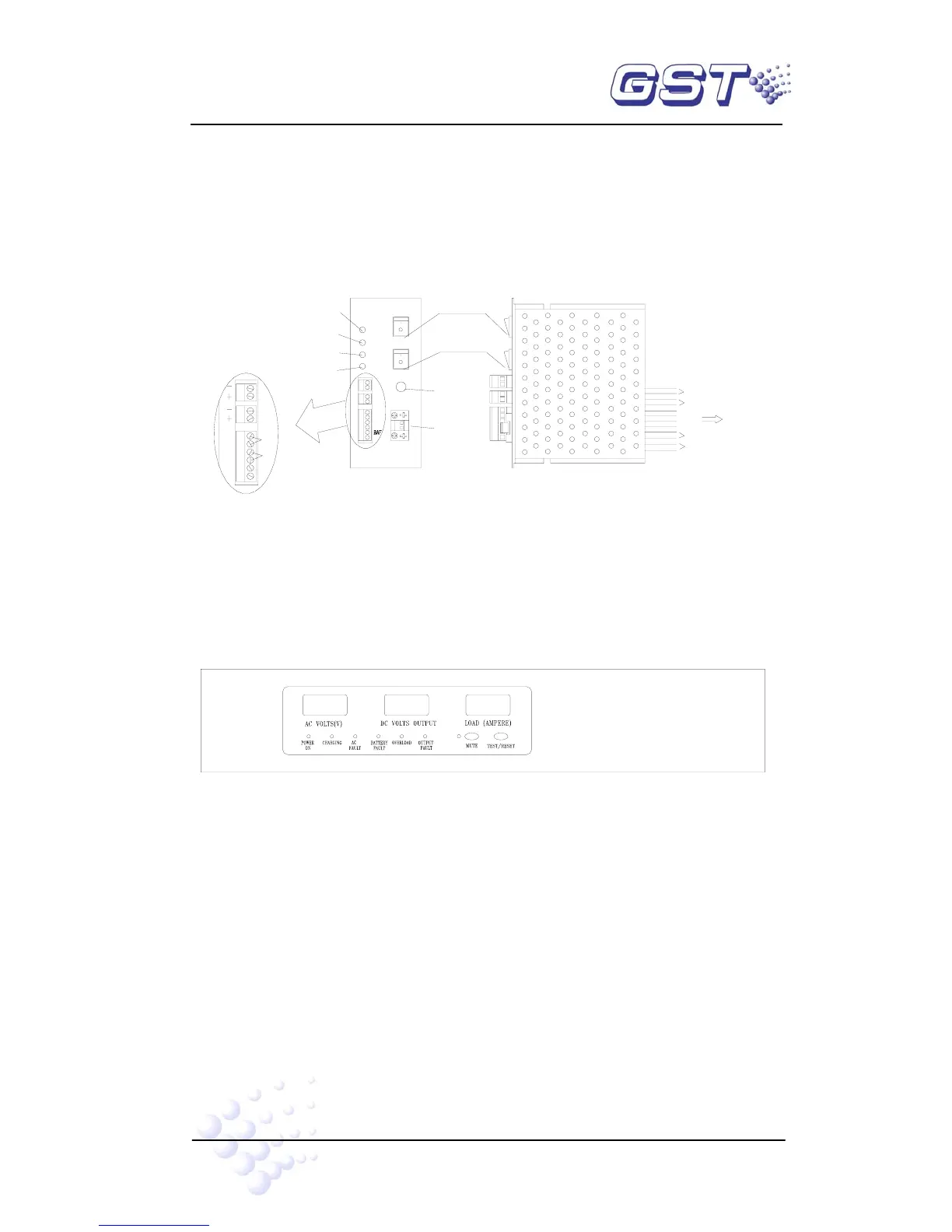
C: Illustration of DC-DC Convertor
DC-DC converting module is shown in Fig. 3-7.
GND
ACF
BATTERY
FUSE(10A)
BATTERY
+5V1
GND1
BAF
+5V2
GND2
Battery Fuse
RUN
Battery Switch
Work Switch
1
2
BAT
BAT
Battery Terminal
5V
MAIN
5V
24V
COM
Main Power 5V LED
Communication 5V LED
Main power 24V LED
+5V1
+5V1
24V
ACF
GND
Work LED
WORK
GND1
GND1
Motherboard XP3
DC-DC CONVERTOR
24V
Battery Check
AC Check
+24V
GND
Switch Board 5V
Display Board 5V
Printer
Fig. 3-7
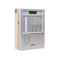
② PSU24-6RM Intelligent PSU
PSU24-6RM intelligent PSU is used to supply power to modules and corresponding
controlled devices.
PSU24-6RM is shown in Fig. 3-8.
INTELLIGENT PSU
Fig. 3-8
A Indicators and switches:
MUTE Key: Pressing MUTE can silence the PSU panel when fault occurs. The
sound will resume when new fault occurs.
TEST/RESET Key: Under monitoring state, this is TEST key, testing all display
components as pressing it, which should be normally lit; after self-test, press
TEST key again, it will self-test again. Under fault state, this is RESET key to
clear the fault. RESET key can clear the fault display and fault alarm sound.
POWER ON LED: Green. For AC power indication.
CHARGING LED: Green. Indicating the charging mode.
AC FAULT LED: Yellow. Lit when AC power voltage is higher than 260VAC or