4.1.2 Detailed design of FlexxPump 402B
The FlexxPump 402B consists of the following elements:
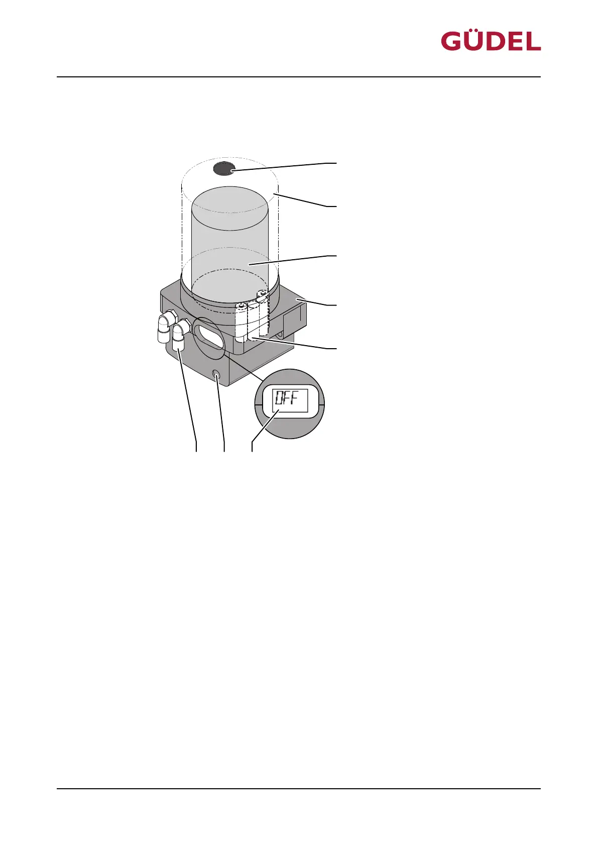
Fig.4-3 Detailed design of FlexxPump 402B
A Vent locking mechanism, including mag-
netic peg
E Battery
B Covering F LCD display
C Cartridge G Active surface
D Casing H Hydraulic outputs
Design, function
OPERATING MANUAL Automatic lubrication system
FlexxPump 402 / 402B
90071992656444683_v9.0_EN-US
37