Adjustments and tool changes
Operational readiness when using grooving tools
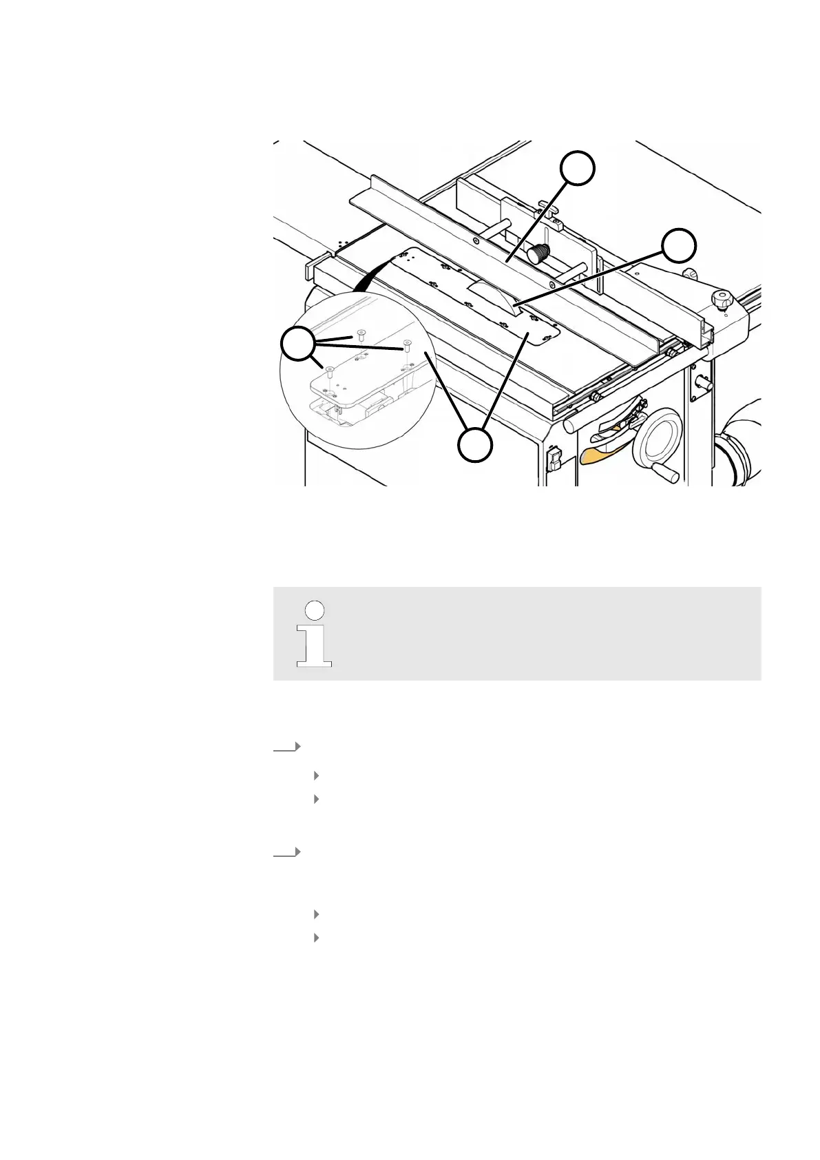
Fig. 9: Operational readiness - grooving tool
1 Insert board (Art.-no. 500-07-206)
2 Flat head screws M6x16
3 Tenoning hood "Sägeboy"
4 Grooving tool
Operational readiness
T
he saw blade only operates if the limit switch inside the machine
frame has not been actuated by the locking system.
Tool:
● Allen key 4 mm
1.
Inserting the insert board.
Position the insert board in the machine table from above.
Screw in 7 countersunk screws with an Allen key.
🡆
The insert board must sit flush with the machine table.
2.
Mount the tenoning hood and "Sägeboy" auxiliary fence to the rip fence.
⮫
Chapter 1.1.4 ‘Mounting the "Sägeboy" auxiliary fence to the rip fence’
on page 7
Clamp the Sägeboy to the rip fence with thumb screws.
Adjust the rip fence so that the tool is covered by the Sägeboy guide
r
ail.
🡆
Assembly, operation and adjustment: See own operating instructions.