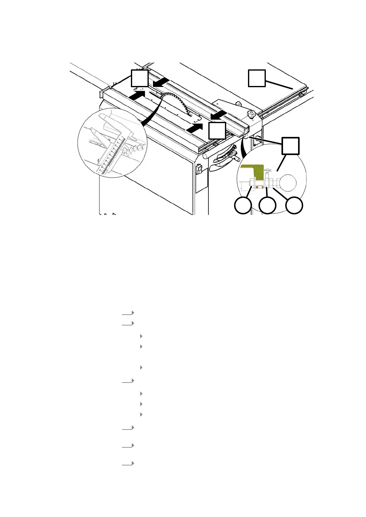
Correcting the rip fence angle (adjust free cut)
Fig. 39: Adjust free cut
1 Locking nut
2 front adjusting nut
3 rear locking nut
A Adjustment point (machine table)
B Adjustment point (table extension)
X1 Rip fence setting
X2 Free cut adjustment
Tool:
● Combination wrench 17 mm
● Callipers
T
he free cut dimension is measured between the saw blade tooth and the fence
plate (guide) on the rip fence.
1.
Loosen the lock nuts at the adjustment points "A" and "B".
2.
On setting point "A" (machine table):
Loosen the rear locking nut.
Adjust the free cut accurately using the front adjustment nut.
🡆
X2 dimension = X1 dimension + 0.07 mm.
Lightly tighten the fixing nut and the locking nut.
3.
At set point "B" (cutting extension):
Loosen the rear locking nut.
Turn the adjusting nut by hand to the cutting extension.
Lightly tighten the fixing nut and the locking nut.
4.
At adjustment points "A" and "B", tighten the lock nuts and fixing nuts
f
irmly.
5.
Prepare the machine to operate. ⮫Chapter 1.3.3 ‘Establish operational
readiness’ on page 12
6.
Check settings with a sample cut using an MDF panel. ⮫
Chapter 2.3.5
‘Longitudinal cut / cutting of strips’ on page 29