MM-013994-001, Rev. J
7
TABLE OF CONTENTS
Page
10.33 RADIO TEXTLINK OPERATION ........................................................................................... 88
10.33.1 Send TextLink Messages ............................................................................................... 88
10.33.2 View Received TextLink Messages .............................................................................. 88
10.33.3 Delete TextLink Messages ............................................................................................ 89
10.33.4 View the Current Time .................................................................................................. 89
10.34 VIEW GPS INFORMATION ..................................................................................................... 89
10.35 CONTROL AND STATUS SERVICES .................................................................................... 89
11 PREVENTIVE MAINTENANCE ...................................................................................................... 90
11.1 IMMERSIBLE P7300 PREVENTIVE MAINTENANCE ......................................................... 90
11.2 TECHNICAL ASSISTANCE – IMMERSIBLE P7300 ............................................................. 90
11.3 BASIC TROUBLESHOOTING ................................................................................................. 90
12 CUSTOMER SERVICE ...................................................................................................................... 92
12.1 CUSTOMER CARE ................................................................................................................... 92
12.2 TECHNICAL ASSISTANCE .................................................................................................... 92
13 WARRANTY ........................................................................................................................................ 93
FIGURES
Figure 5-1: Removing the Battery Pack ......................................................................................................... 17
Figure 5-2: Attaching the Battery Pack .......................................................................................................... 18
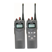
Figure 6-1: P7350 andP7370 Portable Radios ............................................................................................... 19
Figure 6-2: P7300 15-Pin Universal Device Connector ................................................................................ 20
Figure 9-1: Top View ..................................................................................................................................... 24
Figure 9-2: Side View .................................................................................................................................... 24
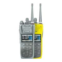
Figure 9-3: P7350 “Scan” Model Front Panel ............................................................................................... 26
Figure 9-4: P7370 “System” Model Front Panel ........................................................................................... 26
Figure 9-5: Sample Radio Display ................................................................................................................. 27
Figure 9-6: Full Cycle Battery Charge Indicator ........................................................................................... 28
Figure 9-7: Tri-Color LED ............................................................................................................................. 28
Figure 9-8: Personality Structure Example .................................................................................................... 30
Figure 10-1: Top View ................................................................................................................................... 59
Figure 10-2: Side View .................................................................................................................................. 59
Figure 10-3: P7350 “Scan” Radio Front Panel .............................................................................................. 61
Figure 10-4: P7370 “System” Radio Front Panel .......................................................................................... 62
Figure 10-5: P7300 Radio Display ................................................................................................................. 63
Figure 10-6: Full Cycle Battery Charge Indicator ......................................................................................... 64
Figure 10-7: Tri-Color LED ........................................................................................................................... 65
Figure 10-8: Menu Display ............................................................................................................................ 69
Figure 10-9: Backlight Menu Item Selection Parameter ................................................................................ 70
Figure 10-10: Backlight Menu Display
......................................................................................................... 70
Figure 10-11: System Encryption Key Display ............................................................................................. 73
Figure 10-12: Group/Channel Encryption Key Display ................................................................................ 73
Figure 10-13: Calls Received Lists ................................................................................................................ 79
Figure 10-14: WHC Individual Call Display ................................................................................................. 80
Figure 10-15: Calls Received and Personality Lists ...................................................................................... 81
Figure 11-1: Labels ........................................................................................................................................ 90
 Loading...