Connection
44 A01185_11_X00_00 HBM: public CANHEAD
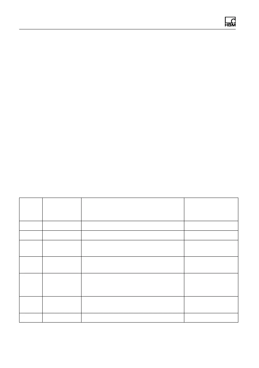
Meaning of the LEDs:
The LEDs indicate the measuring point status whenever there is a ”change of
status”. When an SG is connected to measuring point 1, the green LED flashes
(Status 1) once (corresponding to the measuring point) and then stays on.
1. Green LED: OK, measuring point recognized
2. Red LED:
If there is an error when powering up the system with SGs con
nected, the red LED flashes the number of times to correspond
to the corres‐ ponding error number (Error code, see Table
below) and then stays on (flashes up to error number 32 at
maximum, i.e. 32 times).
The red LED also flashes in measurement mode when there is
a change in status (SG overloaded or SG connected/discon
nected), to correspond to the corresponding measuring point;
should, for example, an SG become disconnected from mea
suring point 8, the red LED will flash 8 times.
Hexa‐
deci
mal
Error num
ber (decimal
value)
Error Remedy
1 1 internal bus error Repair situation
1)
2 2 Error during hardware testing Repair situation
1)
4 4 Setup data (system variables) cannot
be loaded; e.g. bridge excitation voltage
Enter the correct
variable
8 8 Setup data (system constants) cannot
be loaded; e.g. calibration values
Enter the correct
constant
10 16 Errors in certain parameters (e.g. CAN
address) in the system variant or sys
tem constant
Enter the correct
parameter
20 32 Wrong command sent from ML74B to
CANHEAD (STO)
Repair situation
1)
40 64 Execution error Repair situation
1)