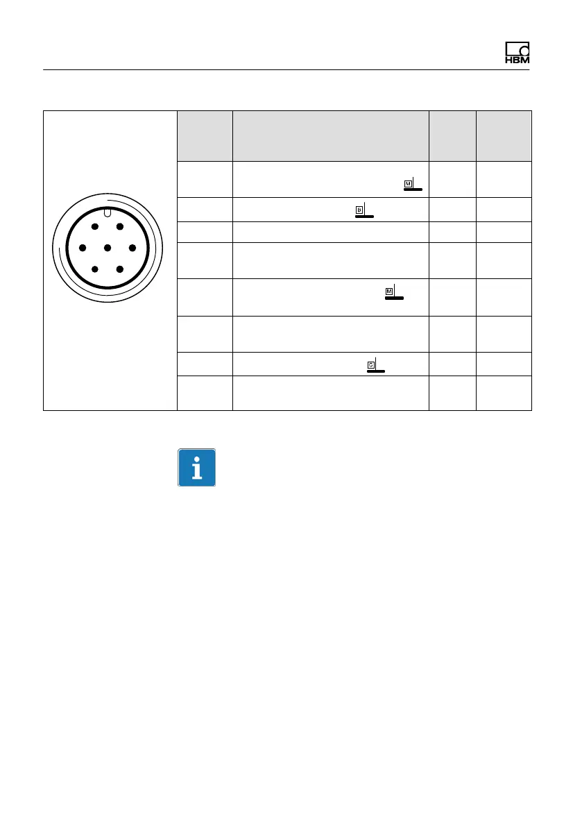
Electrical connection
44 A0608-14.0 HBM: public T10F
61
5
72
4
3
Binder 723
Top view
Binder
conn.
Pin
Assignment Wire
color
Sub‐D
conn.
Pin
1 Torque measurement signal
(frequency output; 5 V
1
; 0 V)
wh 13
2
Supply voltage 0 V;
bk 5
3 Supply voltage 18 V ... 30 V bu 6
4 Torque measurement signal
(frequency output; 5 V
1
/12) V)
rd 12
5
Measurement signal 0 V;
symmetrical
gy 8
6 Calibration signal trigger 5 V -
30 V
gn 14
7
Calibration signal 0 V;
gy 8
Shielding connected to housing
ground
1)
Factory setting; complementary signals RS-422
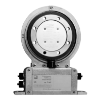
Important
The torque flanges of option 3, code SF1/SU2 are only
intended for operation with a DC supply voltage. They
must not be connected to older HBM amplifiers with
square‐wave excitation. This could lead to the
destruction of the connection board resistances or other
errors in the measuring amplifiers (the torque flange, on
the other hand, is protected and once the proper
connections have been re‐established, is ready for
operation again).