392 Touch Probe Cycles: Automatic Datum Setting
15.13 DATUM IN ONE AXIS (Cycle 419, DIN/ISO: G419)
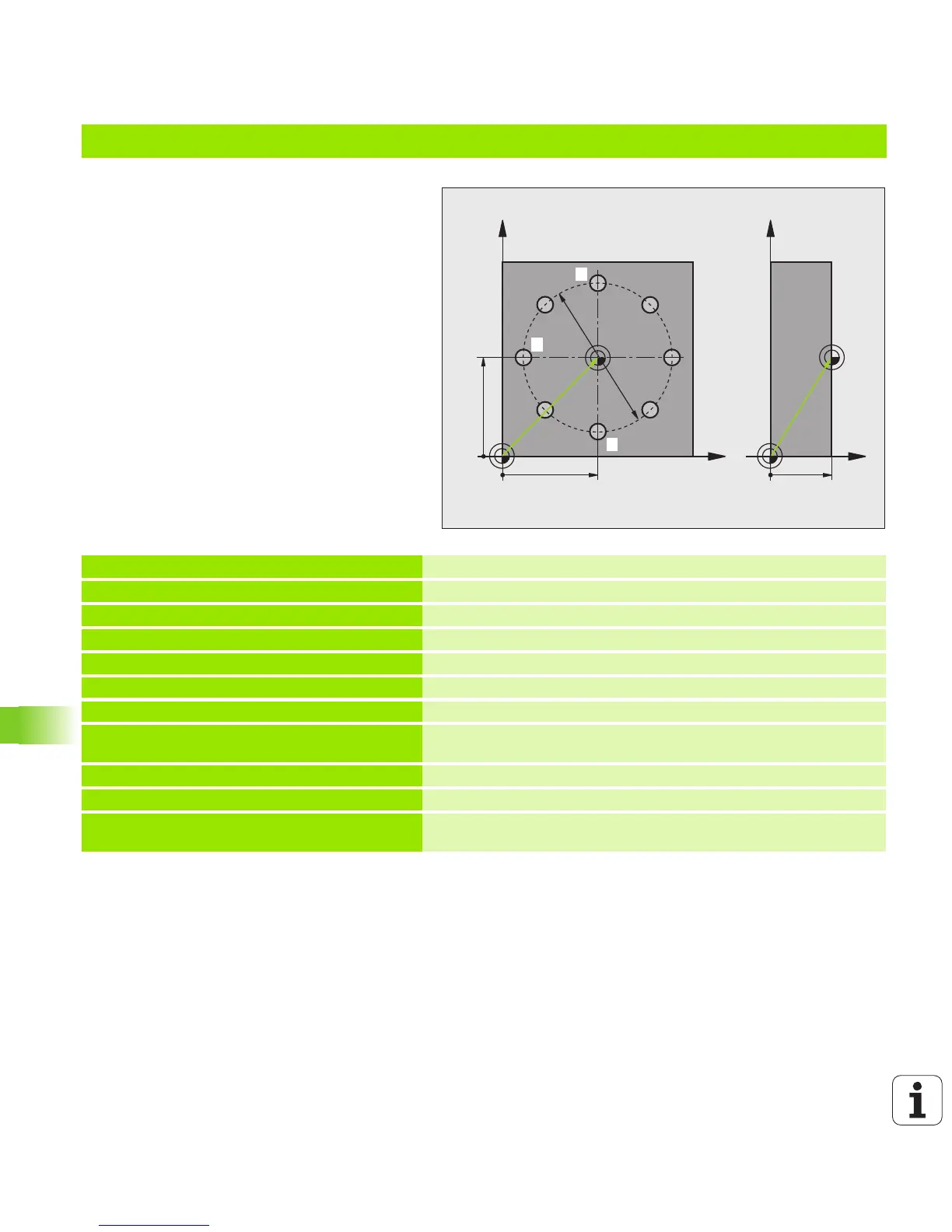
Example: Datum setting on top surface of workpiece and in center of a bolt hole circle
The measured bolt hole center shall be written in
the preset table so that it may be used at a later
time.
0 BEGIN PGM CYC416 MM
1 TOOL CALL 69 Z
Call tool 0 to define the touch probe axis
2 TCH PROBE 417 DATUM IN TS AXIS
Cycle definition for datum setting in the touch probe axis
Q263=+7.5 ;1ST POINT 1ST AXIS
Touch point: X coordinate
Q264=+7.5 ;1ST POINT 2ND AXIS
Touch point: Y coordinate
Q294=+25 ;1ST POINT 3RD AXIS
Touch point: Z coordinate
Q320=0 ;SETUP CLEARANCE
Safety clearance in addition to MP6140
Q260=+50 ;CLEARANCE HEIGHT
Height in the touch probe axis at which the probe can traverse
without collision
Q305=1 ;NO. IN TABLE
Write Z coordinate in line 1
Q333=+0 ;DATUM
Set touch-probe axis to 0
Q303=+1 ;MEAS. VALUE TRANSFER
In the preset table PRESET.PR, save the calculated datum
referenced to the machine-based coordinate system (REF system)

 Loading...