1 Introduction
1.4 Graphics and Status Display
L
3D View
This mode displays the simulated workpiece in
three dimensional space.
-
Rotating the 3D view
In the 3D view, the image can be rotated around
the vertical axis.
The angle of orientation is indicated with a special
symbol:
L
O” rotation
1
90° rotation
1
1 80° rotation
r
270° rotation
\
STRRT )
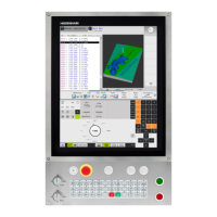
Fig. 1.27: TNC graphic display in 3D view
Fig. 1.28: Rotated 3D view
Shift the soft-key row.
/ pg Or pgg 1
Rotate the part by 90” in the horizontal plane.
TNC 370
1-29

 Loading...


