1
Introduction
d
1.5
Interactive Programming Graphics
The TNC’s interactive graphics generates the part
contour as it is being programmed. Movements in
the negative tool axis direction are displayed as a
circle (circle diameter = tool diameter) to provide
interactive graphics for drilling operations as well.
In addition, the following functions are available:
l
Detail magnification
l
Detail reduction
l
Clearing the graphic
The graphic functions are selected exclusively with
soft keys.
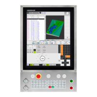
Fig. 1.36: Programming graphics
ff you w&h to work with ttre
pragrammin~
graphics, you must switch the screen tayout to GRAPHICS (Jr TEXT +
GRAPfliCS {see page I-4).
_
Generating graphics during programming
If necessary, shift the soft-key row.
/
I
\
i)
Select/deselect graphic generation during programming. The default
1 setting is OFF.
Generating graphics for an existing program
1
If necessary, shift the soft key row.
Select the desired block with the vertical cursor keys.
Enter the desired block number, e.g. 47.
J-
Generate a graphic from block 1 to the entered block.
I
1 START / 1
I --
1-34
TNC 370 -

 Loading...


