Traffic control
Basic - L3P
Release
3.1
06/07
8.6
VLANs
163
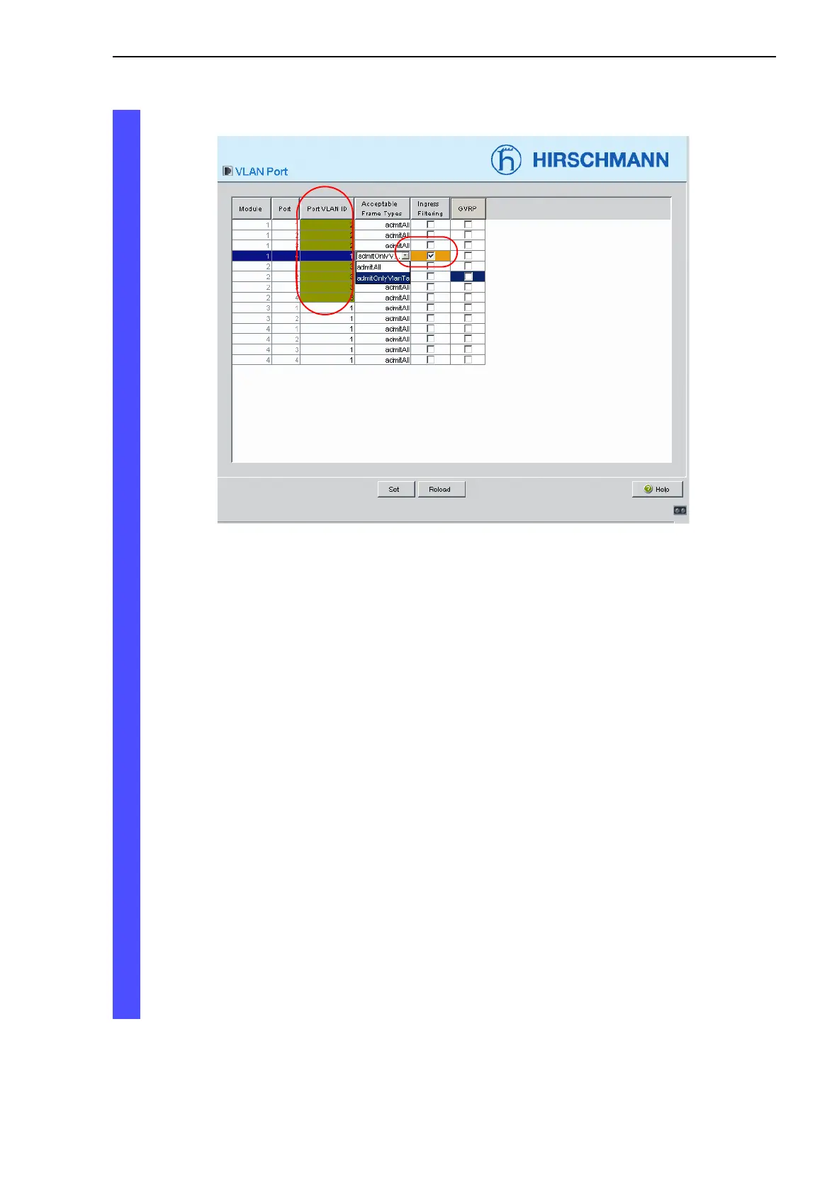
Fig. 49: Assigning the VLAN ID, Acceptable Frame Types and Ingress
Filtering to the ports and saving it
Ports 1.1 to 1.3 are assigned to the terminal devices of the yellow VLAN
and therefore VLAN ID 2 and ports 2.1 to 2.4 are assigned to the termi
-
nal devices of the green VLAN and hence VLAN ID 3. Because terminal
devices usually do not send data packets with a tag, you select the
admitAll setting here.
Port 1.4 serves as an uplink port to the next Switch. It belongs to the
brown VLAN and is thus given the VLAN ID 1.
Because terminal devices
usually do not send data packets with a tag, you select the admitAll
setting here.
Activating GVRP locally and then globally at a later time ensures the
distribution of VLAN information. With this information, the agents
configure the uplink ports on both ends of the uplink line so that they
send data packets of the required VLANS over the uplink connection.
Activating the Ingress Filter ensures that the tags received at the
port are evaluated.