6.3 SETTINGS OF DIP SWITCHES
Quantity and position of Dip switches
0
9
8
7
6
5
4
3
2
1
0
9
8
7
6
5
4
3
2
1
DSW4 DSW5
RSW2
DSW9
DSW6
RSW1
DSW3
DSW7
ON
ON
ON
ON
123456123456
123456
ON
1234
12
ON
1234
Factory setting
! CAUTION
Before setting dips switches, rstly turn off power source and set the
position of the dips switches. If the switches are set without turning off the
power source, the contents of the setting are invalid.
? NOTE
• The mark “n” indicates position of dips switches. Figures show setting
before shipment or after selection.
• Indication position of rotatory switches.
0
9
8
7
6
5
4
3
2
1
Indication
Use athead driver
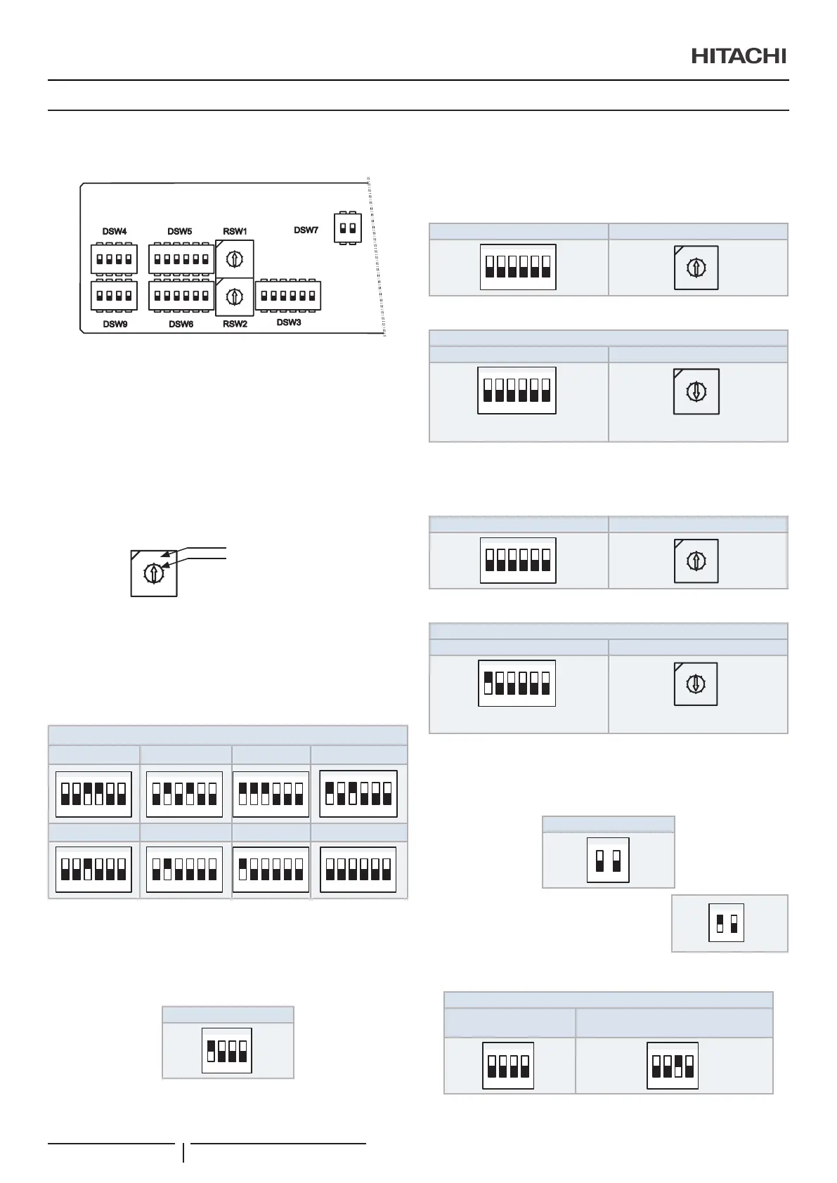
DSW3: Capacity code setting
No setting is required. This dip switch is utilized for setting the
capacity code which corresponds to the Horse Power of the
indoor unit.
Factory setting:
DSW3
1.0 HP 1.5 HP 2.0 HP 2.5 HP
1 2 3 4 5 6
ON
1 2 3 4 5 6
ON
1 2 3 4 5 6
ON
3.0 HP 4.0 HP 5.0 HP 6.0 HP
1 2 3 4 5 6
ON
1 2 3 4 5 6
ON
1 2 3 4 5 6
ON
1 2 3 4 5 6
ON
DSW4: Unit model code setting
No setting is required. This switch is utilized for setting the
model code which corresponds to the indoor unit type.
Factory setting:
DSW4
1234
ON
DSW5 and RSW1: Refrigerant cycle number setting
Setting is required.
Factory setting:
DSW5 RSW1
1 2 3 4 5 6
ON
0
9
8
7
6
5
4
3
2
1
DSW5 and RSW1 can be set up to 63.
Ex. Setting 5 system
DSW5 RSW1
1 2 3 4 5 6
ON
All pins are OFF
0
9
8
7
6
5
4
3
2
1
Fix to 5
DSW6 and RSW2: Unit number setting
Setting is required.
Factory setting:
DSW6 RSW2
1 2 3 4 5 6
ON
0
9
8
7
6
5
4
3
2
1
DSW6 and RSW2 can be set up to 63.
Ex. Setting nº15
DSW6 RSW2
1 2 3 4 5 6
ON
Nº 1 PIN is on
0
9
8
7
6
5
4
3
2
1
Fix to 5
DSW7: Fuse recover
No setting is required.
Factory setting:
DSW7
ON
In case of applying high voltage to the terminal
1,2 of TB2, the fuse (0.5) on the PCB is cut.
In such a case, rstly correct the wiring to TB2
and then turn ON #1 (as showing beside).
12
ON
DSW9:
DSW9
Factory setting
Installation of air panel:
Silent Iconic
ELECTRICAL WIRING
PMML0547 rev.0 - 11/2020
10

 Loading...


