6 ELECTRICAL WIRING
6.1 GENERAL INFORMATION
! DANGER
• Turn off the main power switch to the indoor unit and the
outdoorunitbeforeelectricalwiringworkoraperiodicalcheck
isperformed.
• Checktoensurethattheindoorfanandtheoutdoorfanhave
stoppedbefore electrical wiringwork or aperiodical check is
performed.
• Protect the wires, drain pipe, electrical parts, etc. from rats
or other small animals. If not protected, rats may gnaw at
unprotectedpartsandattheworst,arewilloccur.
! CAUTION
• Install an ELB (Earth Leakage Breaker) in the power source line.
• Use twisted shielded pair cable or shield pair cable for transmission
wires between the indoor and the outdoor units, and connect the
shielded part to the earth screw in the electrical box of the indoor unit
as shown below.
• Wrap the eld supplied insulation around the wires, and plug the
wiring connection hole with the seal material to protect the product
from any condensate water or insects.
• Tightly secure the wires with the cord clamp inside the indoor unit.
• Lead the wires through the knockout hole in the side cover when
using conduit.
• Secure the cable of the remote control switch using the cord clamp
inside the electrical box.
General Check
1 Make sure that the eld-selected electrical components
(main power switches, circuit breakers, wires, conduit
connectors and wire terminals) have been properly selected.
Make sure that the components follow local codes and
regulations.
2 Check to ensure that the power supply voltage is within
+/-10% of the rated voltage.
3 Check the capacity of the electrical wires. If the power
source capacity is too low, the system cannot be started due
to the voltage drop.
4 Select the wire sizes according to the European Standard,
EN60 335-1. Use the wires which are not lighter than
the ordinary tough rubber sheathed exible cord (code
designation 60245 IEC 57) or ordinary polychloroprene
sheathed exible cord (code designation 60245 IEC 57).
5 Check to ensure that the ground wire is connected.
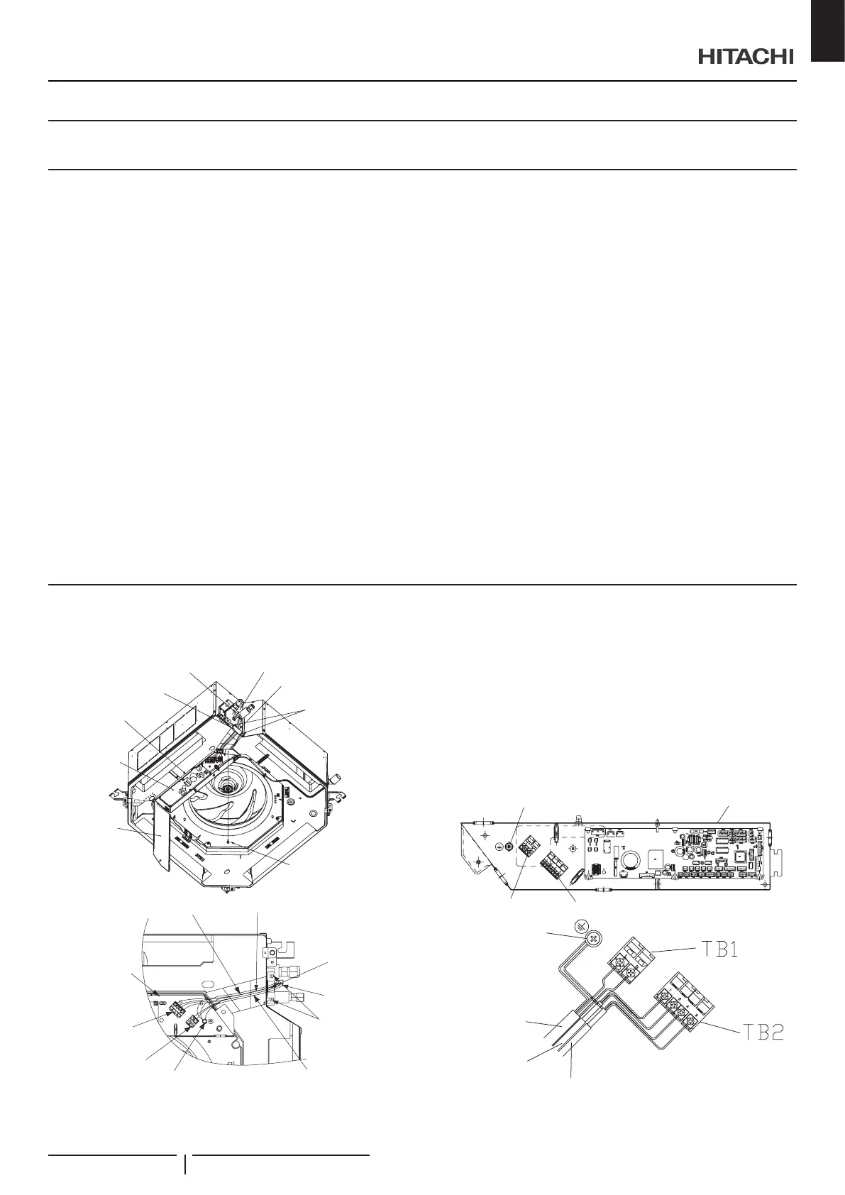
6.2 ELECTRICAL WIRING CONNECTION FOR INDOOR UNIT
1 The electrical wiring connection for the indoor unit is shown
below.
Piping cover
Cord clamp
Wiring support plate
Electrical box
PCB
(Printed circuit
board)
Electrical box
cover
Screw
(for electrical box cover)
Screw for wiring
support plate under
piping cover
Wiring connection hole
Terminal board (black)
1~ 230V 50Hz
Power source wiring
(between indoor units)
Earth wiring connection screw
Screw for wiring
support plate
Cord clamp
Wiring support
plate
Wiring for remote
control switch
Transition wiring between indoor
unit and outdoor unit
Electrical box
Terminal board
(white) DC 5V
2 Remove the electrical box cover (1 screw).
3 Loosen two (2) screws for the wiring support plate.
4 Connect the cable of an remote control switch or an optional
extension cable to the terminals inside the electrical box
through the connecting hole in the cabinet.
5 Connect the power supply and earth wires to the terminals in
the electrical box.
6 Connect the wires between the indoor unit and the outdoor
unit to the terminals in the electrical box.
Electrical box
Earth terminal
Terminal board (TB2)
Terminal board (TB1)
H-Link transmission
wiring (0.75 mm
2
)
Earth
screw
Power source cable
(1~ 230V 50Hz)
(0.75 mm
2
)
Max current: 5 A
Remote control switch cable
ELECTRICAL WIRING
PMML0547 rev.0 - 11/2020
9
EN

 Loading...


