D2 Drive User Guide v1.8 5. Drive Configuration
HIWIN Mikrosystem Corp. 118
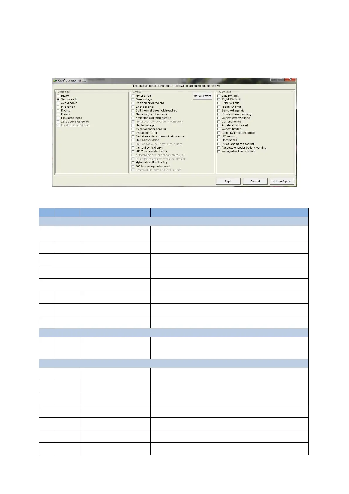
cancelled, click the “Not Configured” button. After selecting the desired function, click the
“Apply” button to complete the setting. On the other hand, click the “Cancel” button to
discard the setting. In the “Errors” category, there is one “Set all errors” button. It is
recommended to use this button at selecting all errors in the “Errors” category. This is
helpful to quickly complete the setting.
Fig. 5-42 Output function setting
Table 5-8
Brake signal. (Checking the brake signal will no longer be
possible to set other status, error, or warning.)
Servo at the enable state.
Servo at the disable state.
Zero speed detection signal.
All errors are normally checked (by clicking the “Set all
error” button). Users can change the combination of errors
to meet the requirement.
Left software limit is triggered.
Right software limit is triggered.
Left hardware limit is triggered.
Right hardware limit is triggered.
PWM command is greater than the set warning value.
Position error is greater than the set warning value.
Velocity error is greater than the set warning value.