D2 Drive User Guide v1.8 6. Drive Tuning
HIWIN Mikrosystem Corp. 168
point-to-point motion.
Fig. 6-27 Acceleration feed-forward
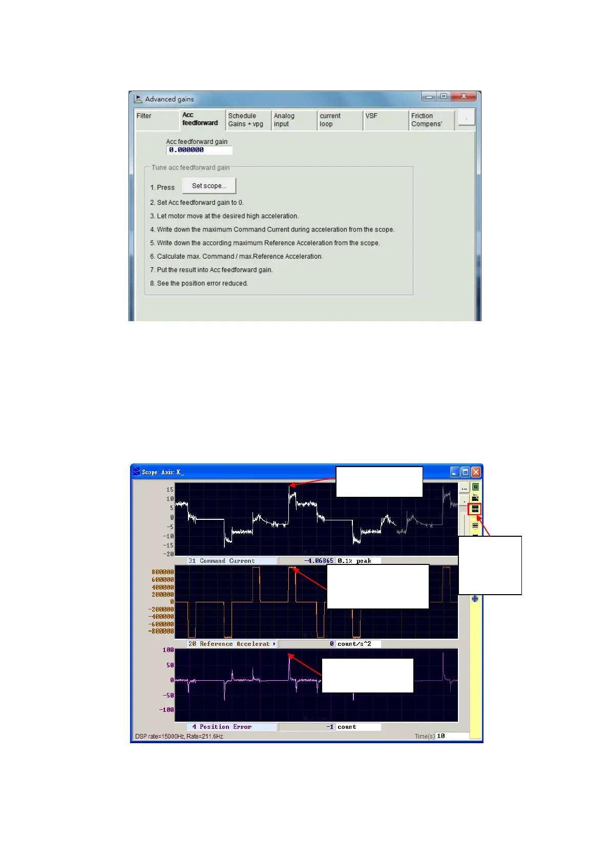
Step 4. Record the maximun of “Command Current” in the acceleration phase, as shown in
Fig. 6-28. It can be observed from the figure that “Command Current” is 16 in the
acceleration phase.
When the motor starts moving, “Scope” will be shown as Fig. 6-28. Use the button of
“Toggle scopes windows (Page UP)” to change to the graph with a single physical
quantity. Repeatedly clicking this button will switch to the graph of “Command
Current”, “Reference Acceleration”, or “Position Error” to facilitate the observation of
graphic value.
Fig. 6-28 Trajectory result of motor movement
Step 5. Record the maximum of “Reference Acceleration” in the acceleration phase. In the
example of Fig. 6-28, the maximum of “Reference Acceleration is 950,000 count/s
2
.
Acceleration” is
2
“Position Error”
is 90 counts.
scopes
windows