D2 Drive User Guide v1.8 6. Drive Tuning
HIWIN Mikrosystem Corp. 183
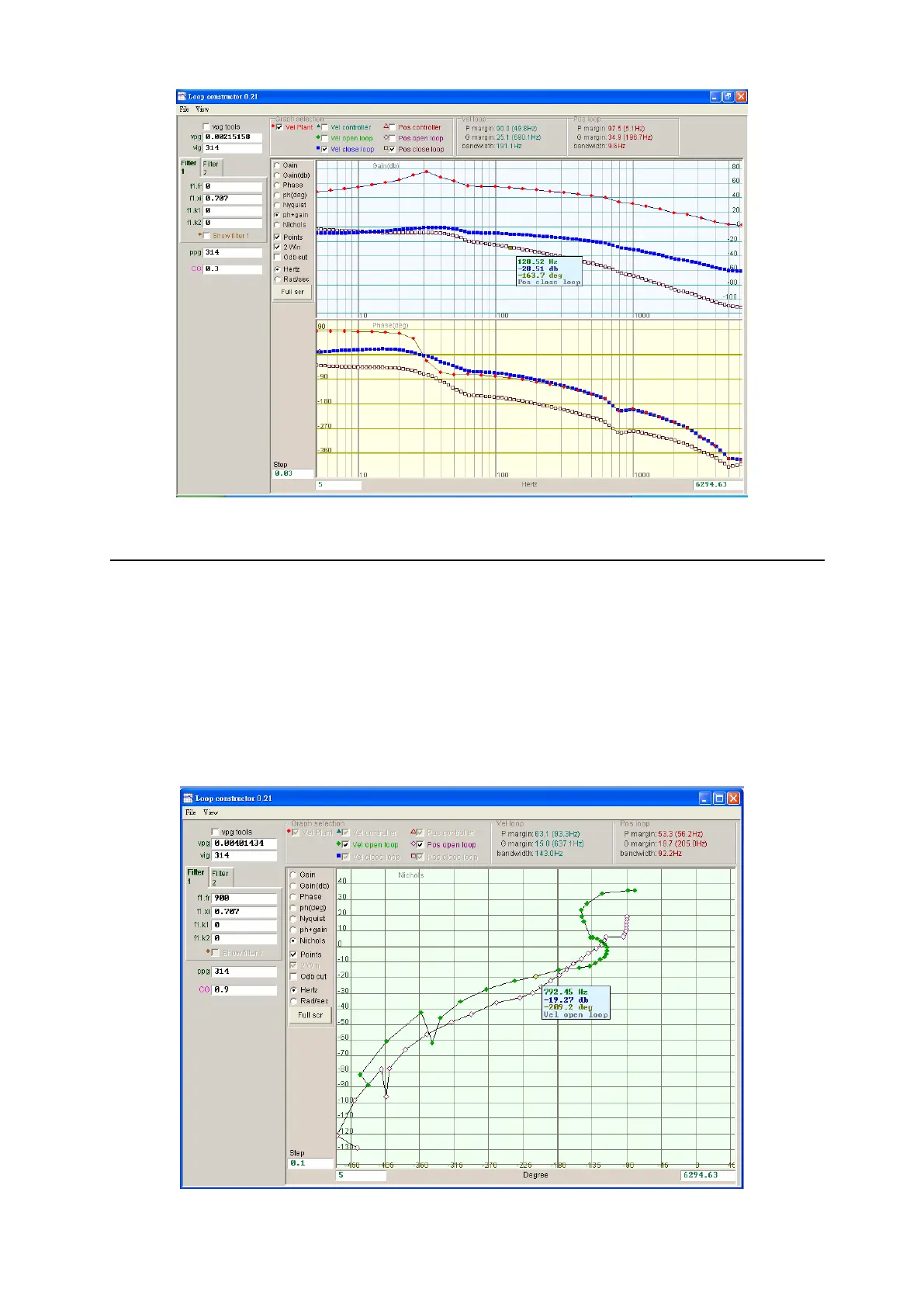
Fig. 6-53 Bode plots of velocity close loop and position close loop
6.7.2.4. Nichols
The “Nichols” option of “Loop constructor” can analyze and simulate frequency responses of
“Vel open loop” and “Pos open loop” of control system. Using the check method can select to
analyze and simulate the Nichols diagram of “Vel open loop” or “Pos open loop”. It can also
select two loops to analyze and simulate at the same time. Nichols plots of “Vel open loop”
and “Pos open loop” are shown in Fig. 6-54. Clicking the curve on the Nichols plot displays the
value of frequency response for the analysis of control system.
(1) Vel open loop (Velocity open loop): The frequency response of the velocity open loop of
control system
(2) Pos open loop (Position open loop): The frequency response of the position open loop of
control system
Fig. 6-54 Nichols plots of velocity open loop and position open loop