D2 Drive User Guide v1.8 8. Protection Function
HIWIN Mikrosystem Corp. 235
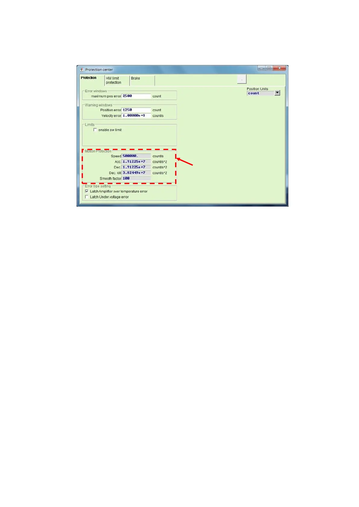
value multiplied by 10 times, to avoid being limited by the motion protection function. If this
action is ignored, the desired speed or acceleration/deceleration may not be achieved when
the motion command is sent from the host controller.
Fig. 8-2
(2) Cancel velocity, acceleration, and deceleration limits
In the position mode, when “Smooth factor” is set to 0, it indicates that drive’s limit
functions of speed, acceleration, and deceleration are canceled, and the motor movement
completely follows the path planning based on the pulse commend sent from the host
controller. Users can decide whether to cancel the drive’s limit function based on the
requirement.
(3) Applicable scope of emergency stop deceleration
The emergency stop deceleration (“Dec. kill”) will be activated in following cases.
A. In the position and velocity modes, it is the deceleration when the motor in motion is
disabled to the emergency stop condition.
B. When executing “P2P” or “Relative move” in the performance center, it is the
deceleration after pressing the “Stop motion” button.
C. When performing the homing procedure, it is the deceleration after finding the home
position.
D. In the “Jog” operation, it is the deceleration after the “Jog” motion is stopped.
“Dec. kill” is used for the case of requiring a high deceleration. Thus, it is recommended to
set “Dec. kill” based on the maximum capacity of motor. The formula for the rotary motor
is described as follows:
Peak current = min (motor peak current, drive peak current).
Dec. kill = (peak current x torque constant)/load inertia.
(4) Smooth motion
The function of smooth motion is used to reduce the impact of motor force to the load in
the acceleration/deceleration phase of motion process. This purpose is achieved by
setting “Smooth factor”. This parameter is designed according to the number of samples
in the moving average filter, as shown in Fig. 8-3. The relationship of filter time constant
and “Smooth factor” is described as follows.
a. Non CoE model: filter time constant = “Smooth factor” × 0.5333 ms;
b. CoE model: filter time constant = “Smooth factor” × 0.5 ms.
Display only and cannot be
modified here.