BF135A•BF150A
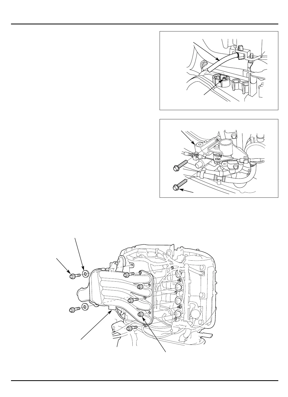
11) Remove the five 8 x 35 mm flange bolts, two 8 mm washers
and the two 8 mm flange nuts. Remove the intake manifold
assembly.
5-130
9) Disconnect the pressure regulator vacuum tube from the
intake manifold joint.
10) Remove the two 8 x 55 mm flange bolts and remove the L.
side cover bracket.
• The L. side cover bracket can be removed without dis-
connecting the cover lock cable.
[1]
PRESSURE
REGULATOR
VACUUM
TUBE
[2]
INTAKE MANIFOLD
JOINT
[1] 8 mm WASHER
[2]
8 mm FLANGE
NUT (2)
[3]
INTAKE MANIFOLD
ASSEMBLY
[1]
L. SIDE COVER BRACKET
8 x 55 (2)
8 x 35 (5)




 To Next Page