15-11
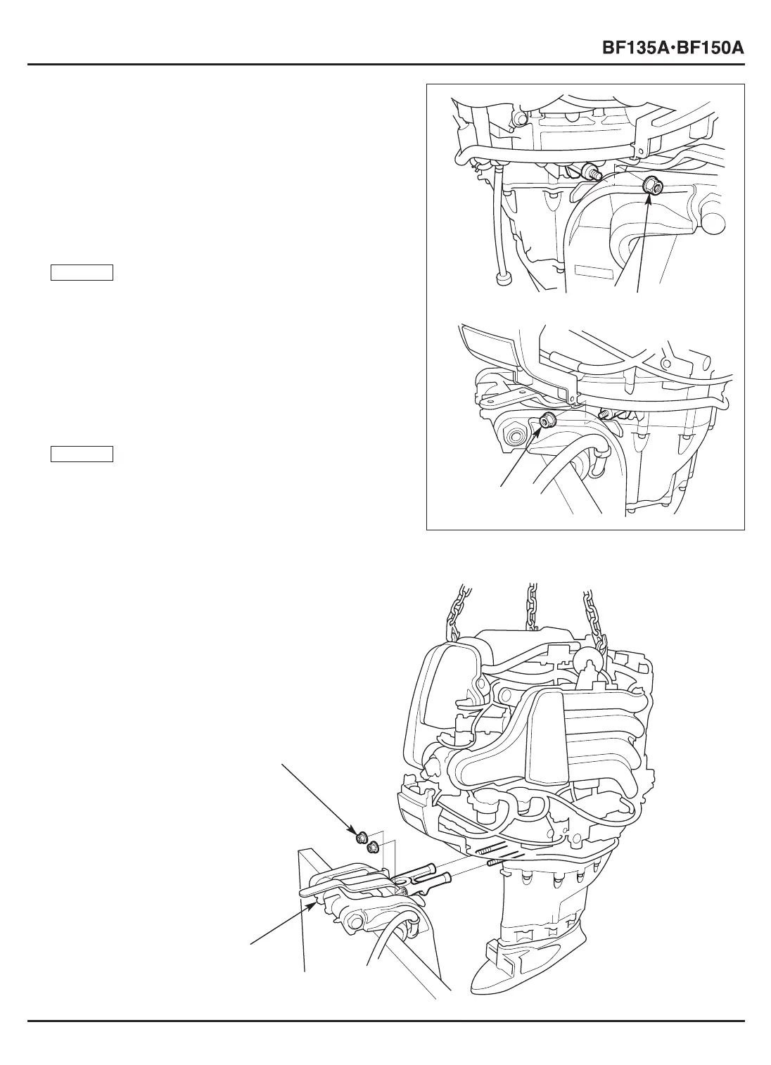
[1] 12 mm SELF-
LOCKING NUT
[1]
12 mm SELF-
LOCKING NUT
[2]
STERN BRACKET/SWIVEL
CASE ASSEMBLY
[1]
12 mm SELF-LOCKING
NUT (2)
5) Swing the outboard motor right and left and remove the
two 12 mm self-locking nuts.
6) Check that the engine assembly/mounting case mating
surfaces are level to the ground.
Holding the outboard motor with the hoist, remove the
stern bracket/swivel case assembly mounted on the
outboard motor stand from the outboard motor.
If it is hard to remove the stern bracket/swivel case
assembly, remove by raising and lowering the outboard
motor slowly with the hoist.
• Do not raise the outboard motor stand off the ground
while raising the outboard motor with the hoist.
• Remove the stern bracket/swivel case assembly with care
not to damage the threads of the two 12 x 145 mm stud
bolts.
7) After removing the stern bracket/swivel case assembly,
lower the outboard motor slowly.
Store the outboard motor with the extension case set on
the ground.
• If it is necessary to store the outboard motor by laying it
on its side, install the L./R. engine under covers (P. 4-14),
drain the engine oil (P. 3-2) and drain the gasoline from
the vapor separator.
• Then, lay the outboard motor on a urethane foam sheet
or blanket with the intake manifold toward down.
NOTICE
NOTICE







 To Next Page