2-64
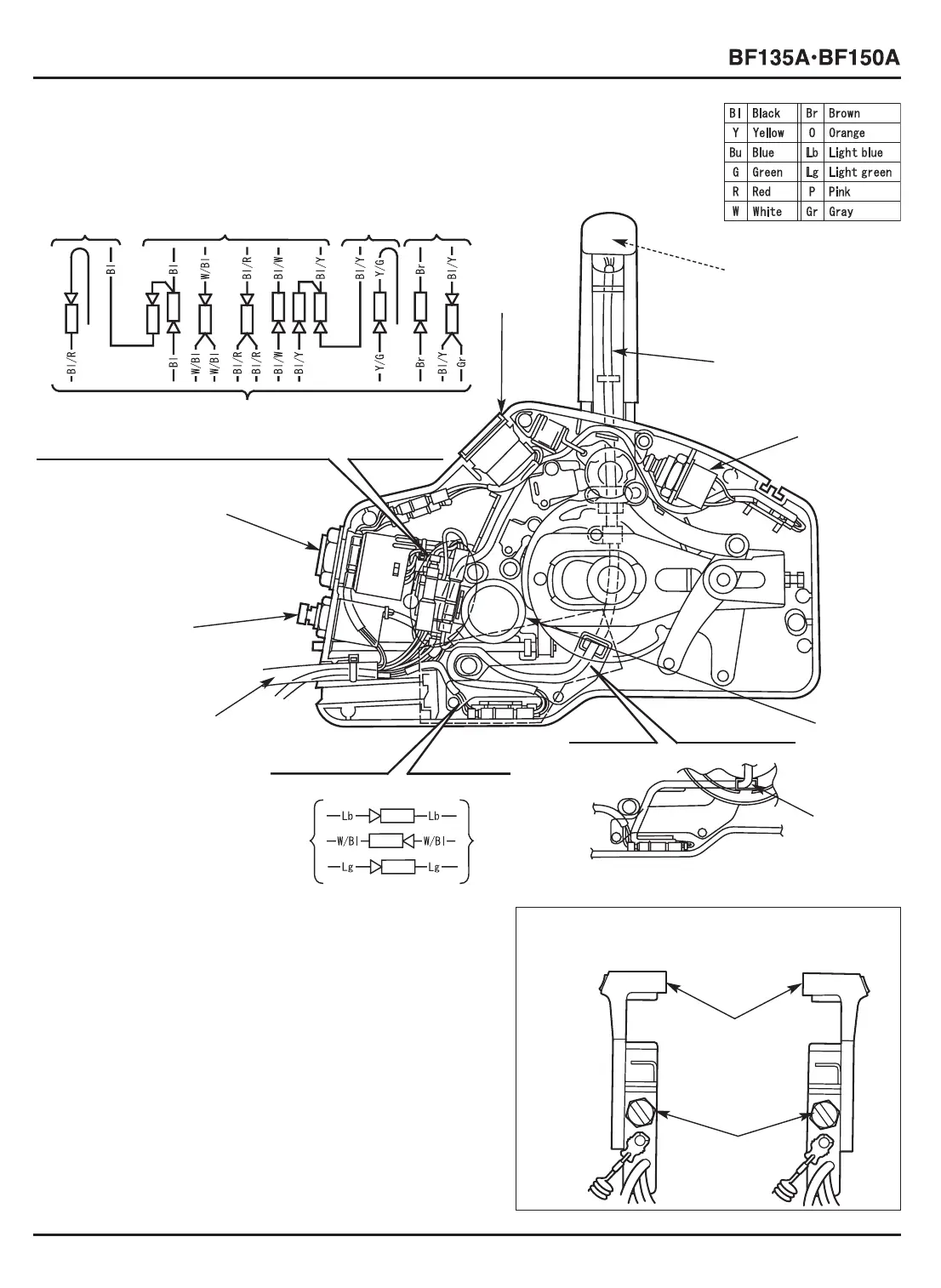
• Side-mount remote control
[6]
INDICATOR
LIGHT
[7] POWER TRIM/TILT
SWITCH
[7]
POWER
TRIM/TILT
SWITCH
[8]
POWER TRIM/TILT
SWITCH WIRE
[4]
SOLENOID
SWITCH
[1]
EMERGENCY
STOP SWITCH
[1]
EMERGENCY
STOP SWITCH
[2]
IGNITION
SWITCH
[2]
IGNITION
SWITCH
[3]
WARNING
BUZZER
[4]
SOLENOID
SWITCH
[3]
WARNING
BUZZER
[5] REMOTE CONTROL CABLE B
[5]
REMOTE
CONTROL
CABLE B
[5] REMOTE CONTROL
CABLE B
*1: Power trim/tilt switch wire routing when the remote
control lever is installed as shown in the drawing A.
*2: Power trim/tilt switch wire routing when the remote
control lever is installed as shown in the drawing B.
*1:
[4] IGNITION
SWITCH
[1] View from ignition switch side:
[5] REMOTE
CONTROL
LEVER
*2:
[8]
POWER
TRIM/TILT
SWITCH
WIRE
[2] DRAWING A
[3] DRAWING B
 Loading...