2-63
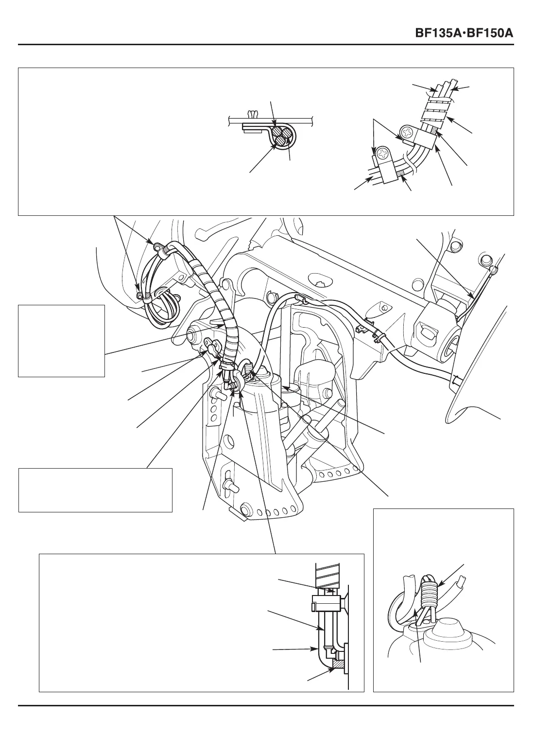
[1] 14 mm CLIPS
• Clamp the power tilt motor wire, trim
angle sensor wire and the speed sensor
tube A.
• Install the 14 mm clip aligning the tape
end of the power tilt motor wire with the
14 mm clip end.
•Tighten the two 5 x 10 mm rivet screws
while pushing the respective 14 mm clips
against the corresponding projection of
the mounting case.
[1]-2
TRIM ANGLE
SENSOR WIRE
[1]-4 PROJECTIONS
[2] GROUND CABLE
[8] TRIM ANGLE
SENSOR WIRE
[9] TRIM ANGLE SENSOR
[1]-1 SPEED SENSOR
TUBE A
[1]-3
POWER
TILT
MOTOR
WIRE
[3] POWER TILT
MOTOR WIRE
[5] MOTOR CORD BUSHING
Pass the power tilt motor wire,
trim angle sensor wire and the
speed sensor tube B through the
motor cord bushing. Align the
tape end of the power tilt motor
wire with the end of the motor
cord bushing.
[5]-1 TRIM ANGLE
SENSOR WIRE
[5]-2 SPEED SENSOR
TUBE A
[6]
SPEED
SENSOR
TUBE B
[5]-3 POWER TILT
MOTOR WIRE
[5]-4 TAPE
[1]-5 TAPE
[1]-5
TAPE
[7] WIRE HARNESS CLIP
Clamp the power tilt motor wire,
trim angle sensor wire and the
speed sensor tube A. Avoid
clamping on the spiral tube.
[10] SPIRAL TUBE
[1]-7
SPIRAL
TUBE
Set the spiral tube
on the power tilt
motor wire, trim
angle sensor wire
and the speed
sensor wire as
shown.
[4] CORRUGATED TUBE
Wind the corrugated tube
around the power tilt motor
wire. Be sure that the tube is
set upright.
[1]-1 SPEED SENSOR
TUBE A
[1]-2 TRIM ANGLE
SENSOR WIRE
[1]-3
POWER
TILT
MOTOR
WIRE
[1]-6
14 mm CLIP (2)
[4]-2 POWER TILT
MOTOR WIRE
[4]-4 CORRUGATED TUBE
 Loading...